 英语
 中文简体
 俄语
 西班牙语
 阿拉伯语

Bienvenido a Hongjia
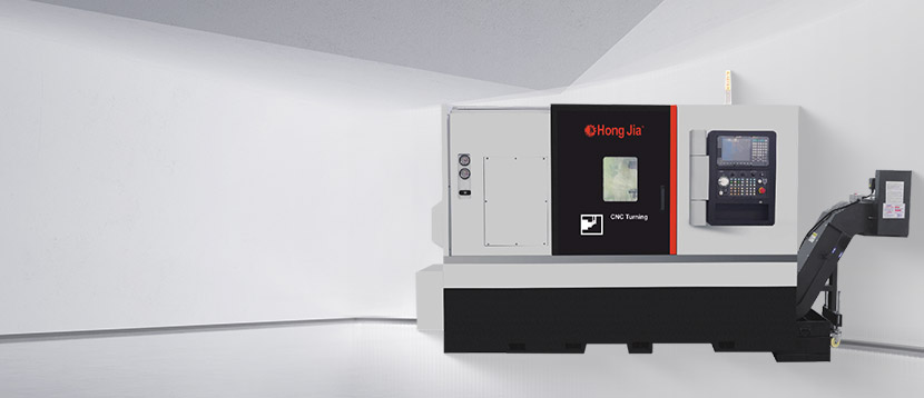
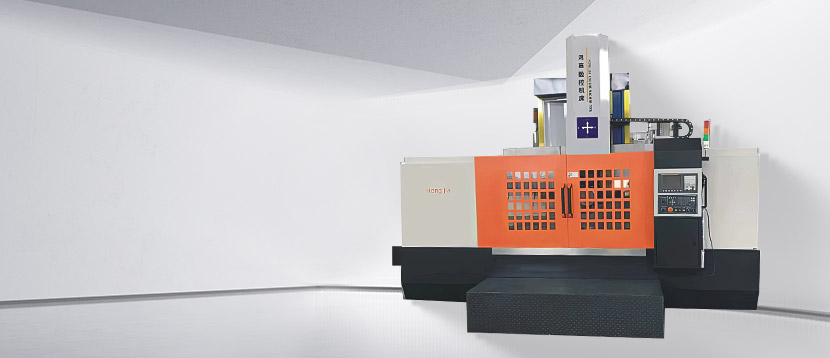
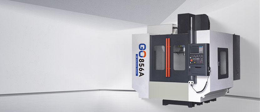
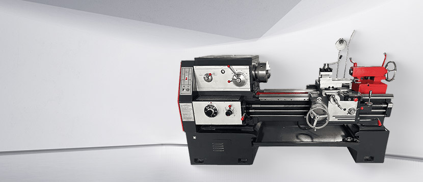
Corte de metales CNC Fabricante especializado
Bienvenido a Hongjia
Bienvenido a Hongjia
Bienvenido a Hongjia
Bienvenido a Hongjia
Bienvenido a Hongjia



Ningbo Hongjia CNC Technology Co., Ltd. comenzó en 2006 y se estableció en 2018. Está ubicada en el Nuevo Distrito de Qianwan, Ciudad de Ningbo, en la Provincia de Zhejiang, en el ala sur de la Zona Económica del Delta del Río Yangtsé de China. Es una empresa especializada en la investigación, desarrollo, producción y ventas de equipos de corte de metal CNC. Con una fuerte capacidad técnica y una rica experiencia en la industria, Hongjia CNC se compromete a ofrecer a los clientes soluciones avanzadas de CNC para satisfacer las necesidades de clientes de diferentes industrias.
Experiencia en la industria
Producción anual
Clientes
Personalizar la configuración según los requisitos del producto del cliente.
Tomar los requisitos del producto del cliente como criterio de aceptación para garantizar que los clientes no se preocupen por comprar máquinas.
Rendimiento de alto costo, ahorro de costos para los clientes.
La tecnología profesional puede resolver el problema de los puntos débiles de los clientes, para que los clientes puedan preocuparse y estar tranquilos.


A first-article inspection on a 316L stainless bone screw often starts with a practical question: can this process hold the critical tolerance across the lot, not just on one good part? That question sits at the center of medical machining. The work is not defined by one machine type. It is defined by a controlled route that matches part geometry, material, tolerance, surface finish, cleaning, and traceability. For buyers, the useful conclusion is simple: choose the process route before comparing machine specifications. A lathe with excellent spindle accuracy will not compensate for a weak fixture or an inspection plan that cannot measure the feature. A modest machine inside a stable, well-documented process can still produce repeatable medical components when the route is right. Start with the Part Family, Not the Machine Medical machining covers surgical instruments, implant components, diagnostic equipment parts, fluid-path connectors, and instrument housings. They do not share one manufacturing recipe. A round bone screw, a flat instrument plate, and a manifold with cross-drilled holes pull the process toward different equipment and inspection methods. A practical way to plan the route is to group parts by dominant geometry. The table below is a starting point for a quote review, not a substitute for a part-specific process plan. Part family, typical process route, and inspection focus for medical machining projects. Part family Typical route Machine features to verify Inspection focus Round implants, screws, pins CNC turning, sometimes second-operation milling Spindle accuracy, collet or chuck repeatability, bar feed Diameter, thread, runout, surface finish Shafts and connectors with two-end features Turning center or dual-spindle turning Spindle synchronization, subspindle, tool clearance Axial alignment, feature-to-feature position Instrument plates and housings Milling, drilling, and tapping Rigidity, thermal stability, small-tool capability Flatness, hole position, burr control Fluid-path and manifold parts Milling plus drilling, deburr, cleaning Coolant pressure, chip evacuation, tool access Cross-hole intersection, cleanliness Prototype or bridge parts Three-axis or four-axis milling, turning Quick setup, work offset, tool library First-article correlation Turning Handles the Round, Repeated Features If the part is mostly rotational, turning is usually the first operation to examine. Medical machining often involves small diameters, fine threads, tapers, radii, and face features that must repeat across thousands of parts. The machine has to hold size without constant operator adjustment. That puts spindle thermal behavior, chuck or collet repeatability, turret positioning, and coolant delivery ahead of headline spindle speed. For a high-precision horizontal lathe, the CK6140 is a relevant starting point when the part envelope and production volume fit a single-spindle layout. It is not a substitute for process validation, but it can be the stable turning platform around which the route is built. For a broader comparison of turning and milling configurations, the turning and milling machine selection guide is useful before narrowing the machine list. CK6140 high-precision CNC horizontal latheThe CK6140 series CNC horizontal lathe features high precision, high power, and high rigidity. Its main components and structure are optimally designed, and it is the ...View Product → Materials Set the Cutting Window Material choice changes tooling, speeds, coolant, and inspection. In medical machining, 316L stainless steel, titanium Ti-6Al-4V, cobalt-chrome, PEEK, aluminum 6061, and brass are common enough to warrant separate process assumptions. The same geometry can behave very differently in titanium and brass. 316L stainless steel can work-harden and burr; sharp edges, stable coolant, and careful deburr matter. Ti-6Al-4V has low thermal conductivity, so heat concentrates at the cutting edge; rigidity and coolant strategy are critical. Cobalt-chrome is abrasive and wear-intensive; tool life and surface integrity need close monitoring. PEEK is not a metal; fixturing pressure, stress relief, and cleanliness affect the result. Aluminum 6061 cuts easily but can mark; chip control and surface protection matter. Brass is often free-machining, but lead-free or special grades may change tooling and finish. Do not accept a material list as proof of capability. Ask for the cutting parameters, tooling, and inspection method used on a comparable part. Material certificates and lot traceability belong in the purchase discussion from the first quote. Tolerances and Inspection Decide the Process Route Tolerance is not a single number. A plus or minus 0.01 mm diameter, a 0.005 mm true position, and a 0.2 micrometer Ra surface finish are different problems. Medical machining quotes should identify which features drive the process, which are functional, and which are reference-only. That distinction prevents over-machining and reduces cost. A workable inspection sequence is: Review the drawing and define the datum scheme before quoting. Verify the machine and fixture can repeat the critical feature in a trial cut. Measure the first article on a CMM, optical comparator, micrometer, or profilometer as the feature requires. Run a capability check on the tightest functional feature, not just the easiest one. Document adjustments and re-check after any tool or program change. When parts have features on both ends, re-fixturing can introduce the error that inspection later finds. A dual-spindle automatic docking turning center, such as the NC106DS, is worth evaluating when the part family has repeated two-end work and the volume justifies the setup. The benefit is not the machine name; it is fewer setups, fewer datum shifts, and a shorter path from blank to verified part. NC106DS Dual-Spindle Automatic Docking Turning CenterFor repeated two-end work, its dual-spindle automatic docking integrates turning, drilling, boring, milling and tapping to reduce setups and datum shifts.View Product → Hole Making and Milling Need Their Own Checkpoints Many medical parts are not finished on a lathe. Instrument plates, housings, manifolds, and fixture components need flatness, pocket depth, hole position, thread quality, and burr control. A vertical machining center or drilling and tapping machine may be the correct route, but only if the machine can hold position across the lot and evacuate chips from small holes. For small-hole drilling and tapping, check spindle speed at the tool tip, peck-drilling control, coolant pressure and aim, tool runout, and the ability to verify hole position without damaging the surface. A high-speed drilling center such as the T600A is relevant when the part family has many small holes and the process needs fast, repeatable drilling rather than heavy milling. T600A High Speed Drilling CenterFor part families with many small holes, its high-speed spindle and through-spindle oil support fast, repeatable drilling and tapping cycles.View Product → Milling and drilling also raise a cleaning question. Burrs and trapped chips are not cosmetic issues in medical machining; they can affect fit, function, and downstream cleaning validation. Specify deburr method, edge break, and inspection access before the first cut. Cleaning, Traceability, and Validation Are Part of the Process A machined part that measures well but cannot be traced is not a finished medical component. The process should preserve material lot, machine, program revision, tool change, operator, inspection result, and cleaning record. This does not mean every buyer needs a full validation package, but the quote should state what is included. Material certificate and lot traceability to the received stock. Process routing with critical operations, fixtures, and inspection points. First-article inspection report with dimensional and surface results. Tool change and program revision control for repeat orders. Cleaning and deburr method, including passivation requirements where applicable. Nonconformance handling and deviation approval before shipment. For regulated work, ask how the supplier validates a new process and how it controls changes. A process that is stable only because the original operator knows the quirks is a supply risk, not a capability. Supplier Questions That Separate Capability from Brochure Claims The fastest way to evaluate a medical machining supplier is to ask for evidence tied to a part family, not a general capability statement. A supplier that cannot explain its fixture, inspection, and change-control logic for a comparable part is unlikely to improve after the purchase order. Which feature on this part will be hardest to hold, and how will you prove capability? What machine, fixture, and tooling will run the first article? How do you compensate for thermal growth during a long run? What is the inspection method for the tightest callout, and who reviews it? How do you control program revisions and tool changes after approval? What cleaning and deburr steps occur before final inspection? What happens when a dimension trends out of tolerance mid-lot? It also helps to review the supplier’s actual equipment and process background. Hongjia CNC’s about page describes a CNC metal-cutting equipment background and a product range that includes horizontal turning centers, vertical lathes, machining centers, and drilling and tapping machines. That range is useful context, but the buyer still needs a part-specific route, a measurable acceptance plan, and a clear change-control process. Medical machining is a discipline of repeatability. The buying sequence should be: define the part family, choose the process route, verify the machine and fixture on the critical feature, lock inspection and traceability, then compare price. A machine quotation without that sequence is only a starting point. The stronger question is whether the supplier can show how the first good part becomes the thousandth good part. .article-section { box-sizing: border-box; width: 100%; margin: 0 0 24px; padding: 28px 30px; border-radius: 18px; background: #ffffff; color: #243244; box-shadow: 0 10px 30px rgba(15, 23, 42, 0.06); overflow: hidden; position: relative; } .article-section + .article-section { margin-top: 22px; } .article-section h2 { font-size: 22px; font-weight: bold; text-align: left; margin-bottom: 12px !important; color: #14213d; line-height: 1.3; } .article-section h2::before { display: inline-block; background: #ef8201; color: #ffffff; font-size: 12px; line-height: 1; padding: 7px 8px; border-radius: 7px; margin-right: 10px; vertical-align: middle; letter-spacing: 0.5px; } .article-section h3 { font-size: 16px; font-weight: bold; text-align: left; margin-bottom: 12px; color: #14213d; } .article-section p { font-size: 16px !important; margin-bottom: 12px; line-height: 1.75; color: #334155; } .article-section ol { margin-bottom: 12px; list-style-type: decimal; list-style-position: inside; padding-left: 0; } .article-section ul { margin-bottom: 12px; list-style-type: disc; list-style-position: inside; } .article-section li { list-style: inherit; font-size: 16px; margin-bottom: 6px; line-height: 1.65; } .article-section table { display: table !important; width: 100%; border-collapse: collapse; margin: 18px 0 10px; background: #ffffff; } .article-section thead { display: table-header-group !important; } .article-section tbody { display: table-row-group !important; } .article-section tr { display: table-row !important; } .article-section th { display: table-cell !important; font-weight: bold; border: 1px solid #cccccc; padding: 8px; background: #ef8201; color: #ffffff; text-align: left; font-size: 15px; vertical-align: top; } .article-section td { display: table-cell !important; border: 1px solid #cccccc; padding: 8px; font-size: 15px; vertical-align: top; color: #334155; } .article-section caption { caption-side: bottom; font-size: 16px; margin-bottom: 12px; font-style: italic; color: #808080; text-align: left; padding-top: 8px; } .article-section a:not([data-product-card]) { color: #c46700; font-weight: 600; text-decoration: none; border-bottom: 1px solid rgba(239, 130, 1, 0.45); } .article-section a:not([data-product-card]):hover { color: #ef8201; border-bottom-color: #ef8201; } .article-section a[data-product-card="true"] { display: block; box-sizing: border-box; margin: 18px 0; padding: 16px 18px; border: 1px solid #f2c48e; border-left: 6px solid #ef8201; border-radius: 14px; background: linear-gradient(135deg, #fffaf4 0%, #ffffff 65%); box-shadow: 0 8px 20px rgba(239, 130, 1, 0.08); text-decoration: none; color: #1e293b; transition: transform 0.2s ease, box-shadow 0.2s ease; } .article-section a[data-product-card="true"]:hover { transform: translateY(-2px); box-shadow: 0 12px 26px rgba(239, 130, 1, 0.16); } .article-section a[data-product-card="true"]::before { display: block; font-size: 16px; font-weight: 700; color: #14213d; margin-bottom: 5px; } .article-section a[data-product-card="true"]::after { display: inline-block; font-size: 14px; font-weight: 600; color: #ef8201; } .opening-section { background: linear-gradient(135deg, #fff7ec 0%, #ffffff 68%); border: 1px solid #f4d5b2; border-left: 8px solid #ef8201; padding-top: 30px; } .opening-section p:first-of-type { font-size: 16px !important; font-weight: 600; color: #172033; } .opening-section p:last-child { margin-bottom: 0; } .opening-section::after { content: ""; position: absolute; right: -40px; top: -50px; width: 170px; height: 170px; border-radius: 50%; background: rgba(239, 130, 1, 0.08); } .part-family-section { background: #f8fafc; border: 1px solid #dbe4ee; } .part-family-section h2::before { content: "01"; } .part-family-section table { box-shadow: 0 8px 20px rgba(15, 23, 42, 0.05); } .part-family-section th { background: #1f2a44; color: #ffffff; border-color: #1f2a44; } .part-family-section td { border-color: #d7e0ea; background: #ffffff; } .part-family-section tbody tr:nth-child(even) td { background: #fff8ef; } .turning-section { background: #ffffff; border-top: 6px solid #ef8201; box-shadow: 0 14px 34px rgba(15, 23, 42, 0.08); } .turning-section h2::before { content: "02"; } .turning-section p:first-of-type { border-left: 4px solid #ef8201; padding-left: 16px; background: #fffaf4; } .turning-section a[data-product-card="true"]::before { content: "CK6140 high-precision CNC horizontal lathe"; } .turning-section a[data-product-card="true"]::after { content: "View machine details"; } .materials-section { background: #fffdf7; border: 1px dashed #ef8201; border-radius: 20px; } .materials-section h2::before { content: "03"; background: #7c4a12; } .materials-section ul { columns: 2; column-gap: 32px; } .materials-section li { background: #ffffff; border: 1px solid #f1dfc8; border-radius: 10px; padding: 9px 12px; margin: 0 0 10px; break-inside: avoid; list-style-position: inside; } .materials-section p:last-child { margin-bottom: 0; color: #4b3a28; font-style: italic; } .tolerance-section { background: linear-gradient(135deg, #101b2d 0%, #17263d 100%); color: #e5edf7; border: 1px solid #273952; } .tolerance-section h2 { color: #ffffff; } .tolerance-section h2::before { content: "04"; background: #ef8201; } .tolerance-section p { color: #dbe6f3; } .tolerance-section ol li { background: rgba(255, 255, 255, 0.06); border-left: 4px solid #ef8201; border-radius: 8px; padding: 10px 12px; margin-bottom: 10px; color: #eaf1f9; } .tolerance-section ol li::marker { color: #ffb45e; font-weight: 700; } .tolerance-section a[data-product-card="true"] { background: linear-gradient(135deg, #fff8ef 0%, #ffffff 70%); border-color: #f0bb7b; } .tolerance-section a[data-product-card="true"]::before { content: "NC106DS dual-spindle automatic docking horizontal turning center"; } .tolerance-section a[data-product-card="true"]::after { content: "View turning center details"; } .hole-section { background: #ffffff; border: 1px solid #e5e7eb; border-left: 7px solid #ef8201; } .hole-section h2::before { content: "05"; } .hole-section p:first-of-type { background: #f4f7fb; border-radius: 12px; padding: 14px 16px; } .hole-section a[data-product-card="true"]::before { content: "T600A high-speed drilling center"; } .hole-section a[data-product-card="true"]::after { content: "View drilling center details"; } .traceability-section { background: linear-gradient(180deg, #ffffff 0%, #fffaf4 100%); border: 1px solid #f0d8bd; border-radius: 18px; } .traceability-section h2::before { content: "06"; background: #14213d; } .traceability-section ul { background: #ffffff; border: 1px solid #f0d8bd; border-radius: 14px; padding: 16px 18px; } .traceability-section li::marker { color: #ef8201; } .traceability-section p:last-child { background: #14213d; color: #ffffff; padding: 14px 16px; border-radius: 12px; margin-bottom: 0; } .supplier-section { background: #f7f9fc; border-top: 6px double #ef8201; box-shadow: none; } .supplier-section h2::before { content: "07"; background: #ef8201; } .supplier-section li { background: #ffffff; border-left: 4px solid #ef8201; border-radius: 0 10px 10px 0; padding: 10px 12px; box-shadow: 0 4px 12px rgba(15, 23, 42, 0.04); } .supplier-section p:last-child { background: #ffffff; border-radius: 12px; padding: 16px; border: 1px solid #e3eaf3; } .closing-section { background: linear-gradient(135deg, #14213d 0%, #1f2a44 58%, #3a2a16 100%); color: #ffffff; border: 1px solid #2d3d58; border-radius: 20px; padding: 32px; } .closing-section p { color: #e7edf6; font-size: 16px !important; } .closing-section p:first-of-type { font-weight: 600; color: #ffffff; } .closing-section p:last-of-type { margin-bottom: 0; color: #ffcf9b; } .product-card{display:block;margin:20px 0;border:1px solid #e5e7eb;border-radius:10px;overflow:hidden;font-style:normal;background:#fff;box-shadow:0 0 5px rgba(31,41,55,.08)} .pc-inner{display:flex;text-decoration:none;color:inherit;align-items:center;min-height:148px} .product-card .pc-img{width:auto!important;min-width:0!important;max-width:min(36%,240px)!important;height:auto!important;min-height:0!important;max-height:148px!important;aspect-ratio:auto!important;object-fit:contain!important;flex:0 0 auto;display:block;align-self:center} .pc-body{padding:12px 16px;flex:1;min-width:0;display:flex;flex-direction:column;align-self:stretch;justify-content:center} .pc-title{display:block;font-size:15px;font-weight:600;color:#111;margin:0 0 6px;line-height:1.4} .pc-desc{display:-webkit-box;font-size:13px;color:#6b7280;margin:0 0 8px;line-height:1.5;overflow:hidden;-webkit-line-clamp:2;line-clamp:2;-webkit-box-orient:vertical} .pc-cta{display:block;font-size:13px;font-weight:600;color:inherit;margin-top:auto} .pc-inner:hover .pc-title{text-decoration:underline} .article-section a:not(.pc-inner),article a:not(.pc-inner){color:inherit}.pc-cta{color:inherit!important}
A request for quotation arrives with a STEP file, a PDF drawing, and a delivery date. Before the shop can quote, it has to answer three questions: can the part be held, can the tool reach every feature, and can the machine hold tolerance at the quoted cycle time. CAD and CAM answer those questions in sequence. CAD defines the part; CAM defines the motion that makes it. The handoff between them is where most estimating errors, scrapped first articles, and unexpected tool changes begin. What CAD and CAM Actually Do CAD is the geometry side of the workflow. It produces the 2D drawing, the 3D model, the assembly structure, and the dimensions and tolerances that define acceptance. In a job shop, the CAD file may come from the customer, or it may be rebuilt from a drawing because the supplied model is incomplete. CAD answers one question: what is the part? CAM starts with that geometry but answers a different question: how is the part made? The programmer defines stock, workholding, tool assemblies, operation sequence, cutting parameters, coolant strategy, and toolpath. The output is not a prettier model. It is a machine-specific set of instructions, usually G-code, plus a setup sheet that tells the operator what to load and where to touch off. CAD and CAM are separate decisions; a clean model does not guarantee a clean toolpath. Question CAD CAM Primary question What is the part? How is it made? Core input Customer drawing, scan, concept 3D model, stock definition, machine kinematics Core output 2D drawing, 3D model, bill of materials Toolpath, NC program, setup sheet Main risk Missing tolerance or datum Wrong post-processor, stock allowance, or tool reach Typical owner Design engineer, drafter CAM programmer, machinist The distinction matters commercially. A design change may cost engineering hours. A CAM change may cost a fixture, a tool, or a prove-out cycle. Treating them as one step hides both costs. The Handoff: Model Quality Becomes Machine Accuracy A model can look perfect on screen and still be unusable in CAM. Open surfaces, overlapping solids, mixed units, and missing datums force the programmer to rebuild geometry, and every rebuild introduces a chance to move a feature. For turned parts, the most important handoff is often the axis of rotation and the stock envelope. If the model centerline does not match the spindle axis in CAM, the part will be cut eccentric no matter how carefully the toolpath is generated. Before programming, check the model against the drawing rather than against the screen: Units and scale. Confirm millimetres or inches before import. A 25.4 factor error can survive several operations before it becomes obvious. Datum scheme. Agree on the A-B-C datums and make the CAM work offset mirror the drawing. Stock condition. Define bar stock, cast blank, or near-net forging; stock changes depth of cut, tool engagement, and cycle time. Feature intent. Threads, chamfers, fillets, undercuts, and reliefs need a purpose. A cosmetic chamfer can become a collision on a back-facing tool. Tolerance stack. CAD shows nominal geometry. It does not show chucking deflection, thermal growth, or the effect of a dull insert. For shops cutting larger bar stock or taking heavy roughing passes, a high-power horizontal lathe with a stable bed gives the programmer room to use realistic depths of cut. CK6150 High-Power CNC Horizontal LatheHigh-power flat-bed lathe with 82 mm spindle bore and 7.5 kW motor, suited to larger bar stock and heavy roughing with matched CAM.View Product → From Toolpath to Machine Motion CAM output is not universal. The post-processor translates a generic toolpath into the code a specific machine expects: tool-change positions, spindle orientation, coolant M-codes, tailstock movement, chuck clamping, bar-feeder handshakes, and subspindle synchronization. A post that is close but not correct can produce a program that looks reasonable on screen and behaves badly at the machine. Machine features change the programming job more than most buyers expect: Axis count. A two-axis lathe and a three-axis turning center with a Y-axis or subspindle require different collision checks and synchronization logic. Turret configuration. The number of stations, live tooling, and dual-turret capability determine whether a feature can be finished in one setup or needs a second operation. Control capability. Macro support, memory, look-ahead, and canned cycles affect how the program is structured and how fast it can run without dwells. Workholding. Chuck, collet, steady rest, and tailstock choices set the stock model and the reachable area. On a heavy-cutting turning center, the programmer must also respect spindle power and torque. A path that looks efficient in software can stall the spindle or create chatter if the depth of cut exceeds what the machine can absorb. NC-106D Heavy-Cutting Horizontal Turning CenterHeavy-cutting turning center with 56 mm spindle bore, 11 kW spindle, and 12-station power turret, worth reviewing when matching CAM to spindle torque and tooling.View Product → Where CAD/CAM Changes the Machine Buying Decision Buying a machine without checking the CAM side is a common and expensive mistake. The machine's travels, spindle bore, chuck size, turret stations, and control options decide which parts can be programmed economically. A large swing over the bed does not help if the spindle bore cannot pass the bar. A fast spindle does not help if the tool changer or control memory limits the program. Machine specifications should be read as CAM constraints, not only as catalogue numbers. Specification CAM question Why it matters Swing and turning length Can the part be held and reached without interference? Sets the work envelope used in CAM Spindle bore and chuck Can the raw bar pass through? Determines stock model and number of setups Turret stations and live tooling Can milling and drilling be done in the same setup? Reduces fixtures and handling Control memory and look-ahead Will the program run at high feed without dwell? Affects surface finish and cycle time Tailstock and steady rest Is the shaft supported? Prevents deflection and chatter The selection logic is covered in more detail in this guide to how to choose a horizontal CNC turning and milling machine. Start with the part family, then the workholding, then the machine. A Practical Checklist Before You Commit The cheapest place to catch a CAD/CAM error is still the computer. The second cheapest is a dry run. The most expensive is a scrapped first article on a machine that is already booked. Get the native CAD file and a neutral STEP file. Check units, datum, and model integrity before quoting. Agree on stock and workholding. Confirm bar size, chuck jaws, fixture clearance, and whether the part needs a tailstock or steady rest. Build the CAM setup with the real machine kinematics. Use the actual turret, tool holders, and post-processor, not a generic demonstrator. Simulate with stock removal and collision checking. Look for rapid moves through the chuck, tool holder interference, and unreachable features. Prove the program and inspect the first article. Verify tool offsets, work offsets, first-cut allowance, and acceptance against the drawing. This sequence is not paperwork. It is the cheapest way to catch a wrong insert radius, a missing chamfer, or a turret that cannot reach the back face. Common Misconceptions and Their Cost CAD/CAM is push-button. CAM still requires decisions about stock, tools, order of operations, and hold points. Software can calculate a path; it cannot decide whether the part will move when the chuck opens. Any post-processor will work. A generic post can produce code that looks right and runs wrong. Tool-change height, spindle orientation, and coolant sequencing are machine-specific for a reason. Simulation proves the part. Simulation proves motion, not dynamics. It will not show chatter from a long boring bar or deflection from a weak setup. The cheapest machine is the cheapest part. If a lower-cost machine adds a second setup, an extra fixture, or a slower cycle, the saving disappears at the quotation stage. Matching the Machine to the Work Horizontal lathes and turning centers suit shaft, disc, and sleeve work where the part rotates around a stable centerline. Vertical lathes are often a better fit for large-diameter, short-length parts because workholding is more stable and loading is simpler. Vertical machining centers handle prismatic parts with faces, pockets, and hole patterns. The CAM setup should follow the same logic: choose the machine that removes the most setups without making the part harder to hold. A horizontal CNC turning and milling series typically spans simple two-axis turning through live-tooling and subspindle configurations. That range matters because the same part family may need a basic lathe today and a turning center next year. For large rings, flanges, and short shafts, a single-column vertical lathe can simplify workholding and reduce the temptation to overhang the part. The CK5116B CNC single-column vertical lathe is one example of that configuration. CK-5116B Siemens 808D Single-Column Vertical LatheSingle-column vertical lathe with 1400 mm hydraulic chuck and 1600 mm max tool post diameter, useful for large rings and flanges where workholding simplicity matters.View Product → CAD and CAM are not software categories to compare on a feature list. They are the handoff between a drawing and a cut part. Get the model clean, define the stock and workholding honestly, post to the actual machine, and treat the first article as a test rather than as production. Done that way, the machine becomes a predictable part of the quote instead of the variable that decides whether the job makes money. .article-section { margin: 0 0 28px; color: #2c2c2c; line-height: 1.72; font-family: -apple-system, BlinkMacSystemFont, "Segoe UI", Arial, sans-serif; } .article-section p { font-size: 16px !important; margin-bottom: 12px; } .article-section h2 { font-size: 22px; font-weight: bold; text-align: left; margin-bottom: 12px !important; padding-left: 14px; border-left: 4px solid #ef8201; color: #1f2933; line-height: 1.35; } .article-section h3 { font-size: 16px; font-weight: bold; text-align: left; margin-bottom: 12px; color: #b35c00; } .article-section ul { margin-bottom: 12px; list-style-type: disc; list-style-position: inside; padding-left: 0; } .article-section ol { margin-bottom: 12px; list-style-type: decimal; list-style-position: inside; padding-left: 0; } .article-section li { list-style: inherit; font-size: 16px; margin-bottom: 6px; } .article-section strong { color: #b35c00; } .article-section table { display: table !important; width: 100%; border-collapse: collapse; margin: 16px 0 20px; background: #ffffff; font-size: 15px; line-height: 1.55; } .article-section thead { display: table-header-group !important; } .article-section tbody { display: table-row-group !important; } .article-section tr { display: table-row !important; } .article-section th { display: table-cell !important; font-weight: bold; border: 1px solid #cccccc; padding: 8px; text-align: left; background: #fff3e2; color: #1f2933; } .article-section td { display: table-cell !important; border: 1px solid #cccccc; padding: 8px; text-align: left; vertical-align: top; } .article-section caption { caption-side: bottom; font-size: 16px; margin-bottom: 12px; font-style: italic; color: #808080; text-align: left; padding-top: 4px; } .article-section tbody tr:nth-child(even) td { background: #fcfcfc; } .article-section a:not([data-product-card="true"]) { color: #b35c00; text-decoration: underline; text-underline-offset: 3px; font-weight: 600; } .article-section a[data-product-card="true"] { display: block; margin: 16px 0 4px; padding: 14px 16px 14px 18px; background: #ffffff; border: 1px solid #f0c48a; border-left: 5px solid #ef8201; border-radius: 8px; color: #1f2933; font-size: 15px; font-weight: 700; text-decoration: none; box-shadow: 0 4px 12px rgba(239, 130, 1, 0.06); } .article-section a[data-product-card="true"]:empty::before { content: "View machine specifications"; color: #b35c00; letter-spacing: 0.2px; } .article-section--intro { padding: 24px 26px 20px; background: linear-gradient(135deg, #fff8ee 0%, #ffffff 70%); border-left: 5px solid #ef8201; border-radius: 0 14px 14px 0; box-shadow: 0 8px 20px rgba(239, 130, 1, 0.06); } .article-section--intro p:first-child { color: #262626; font-weight: 600; } .article-section--intro p:last-child { margin-bottom: 0; } .article-section--compare { padding: 22px 24px; background: #fbfcfd; border: 1px solid #e9edf2; border-radius: 14px; box-shadow: inset 0 4px 0 #ef8201; } .article-section--handoff { padding: 22px 24px; background: #ffffff; border: 1px solid #f0e4d3; border-radius: 14px; } .article-section--motion { padding: 22px 24px; background: #f7f9fb; border: 1px solid #e3e8ee; border-radius: 14px; } .article-section--motion h2 { border-left-color: #c85f00; } .article-section--buying { padding: 22px 24px; background: #fffdf9; border: 1px solid #f2dfc4; border-radius: 14px; box-shadow: 0 6px 18px rgba(0, 0, 0, 0.03); } .article-section--checklist { padding: 24px; background: linear-gradient(180deg, #fffaf3, #ffffff); border: 1px dashed #f0c48a; border-radius: 14px; } .article-section--myths { padding: 22px 24px; background: #f6f8fa; border-left: 5px solid #ef8201; border-radius: 0 14px 14px 0; } .article-section--myths h2 { border-left-color: #c85f00; } .article-section--matching { padding: 22px 24px 6px; background: #ffffff; border-top: 4px solid #ef8201; border-bottom: 1px solid #eeeeee; } .article-section--conclusion { padding: 22px 24px; background: linear-gradient(135deg, #2f2a24, #1f1c18); color: #f7f2ea; border-radius: 14px; } .article-section--conclusion p { color: #f7f2ea; margin-bottom: 0; } .product-card{display:block;margin:20px 0;border:1px solid #e5e7eb;border-radius:10px;overflow:hidden;font-style:normal;background:#fff;box-shadow:0 0 5px rgba(31,41,55,.08)} .pc-inner{display:flex;text-decoration:none;color:inherit;align-items:center;min-height:148px} .product-card .pc-img{width:auto!important;min-width:0!important;max-width:min(36%,240px)!important;height:auto!important;min-height:0!important;max-height:148px!important;aspect-ratio:auto!important;object-fit:contain!important;flex:0 0 auto;display:block;align-self:center} .pc-body{padding:12px 16px;flex:1;min-width:0;display:flex;flex-direction:column;align-self:stretch;justify-content:center} .pc-title{display:block;font-size:15px;font-weight:600;color:#111;margin:0 0 6px;line-height:1.4} .pc-desc{display:-webkit-box;font-size:13px;color:#6b7280;margin:0 0 8px;line-height:1.5;overflow:hidden;-webkit-line-clamp:2;line-clamp:2;-webkit-box-orient:vertical} .pc-cta{display:block;font-size:13px;font-weight:600;color:inherit;margin-top:auto} .pc-inner:hover .pc-title{text-decoration:underline} .article-section a:not(.pc-inner),article a:not(.pc-inner){color:inherit}.pc-cta{color:inherit!important}
Medical Manufacturing Every medical component quote contains a moment of judgment. A bone screw drawing shows thread pitch, head diameter, and a tolerance band of a few microns. The supplier has to decide whether the process can hold it, not just once, but for every part in the lot. That decision is where precision machining for medical devices really begins. It determines the machine, the tool path, the coolant strategy, the measurement method, and the documentation trail. What Counts as Precision Machining for Medical Devices Precision machining for medical devices is a controlled manufacturing process in which CNC equipment produces components with dimensions, surface quality, and material integrity that are repeatable enough to pass regulatory scrutiny and function safely in the human body. In practice, that means several requirements that go beyond a basic machine specification. Critical dimensions commonly need tolerance bands from ±0.005 mm to ±0.013 mm. Surface finish requirements may call for Ra 0.4 µm or lower on implant surfaces. Edges must be burr-free, with no smeared material that could hide cracks or contamination. Material identity and production records must remain traceable from bar stock to finished device. These requirements are not separate. A poorly rigid machine can allow chatter, which damages surface finish. A thermally unstable spindle can cause drift over a long production run, which breaks repeatability. The practical result is that medical-device machining is only as good as the machine platform, the tooling strategy, and the process design. Typical tolerance and surface expectations for common medical device categories. Device Category Typical Components Machining Emphasis Implant-grade parts Bone screws, spinal cages, acetabular shells Tight diameters, thread forms, Ra 0.4 µm or lower Surgical instruments Graspers, scissors, handles, trocars Burr-free edges, repeatable fits, corrosion-resistant finish Diagnostic and wearable housings Enclosures, connectors, sensor bodies Thin walls, precise hole positions, fine exterior surfaces Materials Shape Both the Part and the Machine Choice The material list for medical devices splits into two broad groups: biocompatible metals and high-performance polymers. Each group places different stress on the machine tool and cutting tool. Biocompatible Metals Stainless steel, titanium alloys, and cobalt-chrome are common for implants, fixation devices, and surgical instruments. Titanium is strong and corrosion-resistant, but it also has poor thermal conductivity and a strong tendency to work-harden. That requires stable spindle torque, rigid tool holding, and a disciplined coolant strategy. Medical Polymers PEEK, PEI, and other engineering polymers appear in spinal interbody devices, instrument handles, and radiolucent components. Machining polymers demands sharp geometry, controlled heat, and clean chip evacuation to avoid melting or tearing the material. A machine that produces a good steel part does not automatically produce a good PEEK part. When you select equipment, the question is not just whether the machine can cut these materials. The question is whether the spindle, coolant delivery, chip management, and axis rigidity can hold the required tolerance across a full production shift. Turning Operations That Define Implant and Instrument Quality Many orthopedic components start as bar or rod stock. Bone screws, peg inserts, driver shafts, trial instruments, and thread-forming components all have cylindrical features that are most efficiently produced by turning. In these jobs, the decision is not simply feed rate. It is whether the spindle, turret, and tool path can maintain a stable cut depth in hardened or work-hardening alloys. Shops that need a mechanically stable platform for this type of work often start with a precision turning center designed for low vibration and good thermal behavior. The machine has to hold a repeatable relationship between the spindle, the tool tip, and the finished diameter over long cycles. Once that basic relationship is stable, the rest of the process can be optimized around tooling, coolant pressure, and in-process measurement. NC110 Precision Mechanical Spindle Horizontal Turning CenterDesigned for stable small cylindrical turning, this center combines a hydraulic three-jaw chuck and built-in high-speed spindle with a rigid structure for repeatable precision and efficient cutting.View Product → For small cylindrical parts, the turning center is often the highest-risk operation in the entire process. If turning is unstable, no amount of downstream milling correction can restore the tolerance. Milling and Drilling for Complex Geometries and Hole Patterns Surgical instrument housings, drill guides, bone cutting guides, and diagnostic enclosures often contain milled pockets, thin webs, and multiple hole positions. A single setup on a capable machining center is usually safer than moving a part through several manual machine stages. For medical-device work, a machining center needs more than axis speed. It needs predictable rigidity, good chip evacuation, and enough program capability to handle fine finishing passes and tight positional tolerances. High-speed drilling and tapping operations also place heavy demand on synchronized axis movement and tool-change repeatability. 1165A High-Speed High-Precision Heavy-Duty Machining CenterWith a wide, heavy-load bed, imported linear guides, and pre-tensioned axis screws, this machining center supports high-speed drilling, tapping, and fine finishing for tight-tolerance medical parts.View Product → Typical Medical Machining Sequences on a CNC Mill Face mill critical mating surfaces to establish flatness. Finish contour pockets and cavities with light radial cuts. Drill and ream guide holes that align with companion components. Deburr and verify edges before the part moves to cleaning and inspection. Quality Systems and Process Control That Protect Patients The machine itself only creates geometry. The system around it creates confidence. In medical-device manufacturing, a single good first article is not enough. The process must deliver the same result in lot after lot, on different operators, different shifts, and different raw material batches. Process Controls In-process probing before critical features are finished Tool wear monitoring and automatic compensation Coolant pressure and temperature control Machine calibration records linked to production batches Documentation Reality A medical process may need to satisfy ISO 13485 requirements. The CNC machine builder does not certify your device, but it should supply calibration documentation, electrical and mechanical specifications, and maintenance guidance that support your validation. Without those records, a machine is just hardware. When you compare equipment, look at how the control and cycle design support repeatable production. In particular, review how modern turning and milling platforms achieve micron-level machining accuracy. You can also compare machine behavior from the angle of thermal drift, spindle load monitoring, and torque curves rather than only axis speed. These are the parameters that determine whether a tight tolerance survives contact with a difficult material. The path to micron-level machining accuracy depends on more than a fine resolution encoder. Choosing a Partner for Precision Medical Manufacturing A machine tool is a long-term purchase. For medical device manufacturing, what matters is not just the first-article result but the behavior of the system over thousands of cycles. The right machine partner should be able to explain how its equipment handles difficult alloys, thermal growth, chip evacuation, coolant delivery, and service response. Hongjia CNC has more than 20 years of machine-building experience, an annual production capacity of 1,000 machines, and more than 500 customers. That background matters because it means the builder has seen the practical side of metal cutting, not only the marketing side. You can read more about Hongjia CNC's approach to machine building and manufacturing experience. More about Hongjia CNC's machine building background. The devices that end up in an operating room cannot carry a warning label that says "operator skill required." They carry, if only by implication, the repeated precision of the manufacturing system that made them. Precision machining for medical devices turns drawings into that reality only when equipment, process, and quality control all work as one system. .article-section{box-sizing:border-box;width:100%;margin:0 0 36px;padding:32px;border-radius:14px;background:#fff;border:1px solid #ebe5dd;color:#222;} .article-section h2{font-size:22px;font-weight:bold;text-align:left;margin-bottom:12px!important;color:#222;padding-bottom:10px;border-bottom:3px solid #ef8201;} .article-section h3{font-size:16px;font-weight:bold;text-align:left;margin-bottom:12px;color:#333;} .article-section p{font-size:16px!important;margin-bottom:12px;line-height:1.7;color:#444;} .article-section ul{margin-bottom:12px;list-style-type:disc;list-style-position:inside;padding-left:0;} .article-section ol{margin-bottom:12px;list-style-type:decimal;list-style-position:inside;padding-left:0;} .article-section li{list-style:inherit;font-size:16px;margin-bottom:6px;line-height:1.6;color:#444;} .article-section a{color:#ef8201;text-decoration:underline;text-underline-offset:2px;} .article-section table{display:table!important;width:100%;border-collapse:collapse;margin-bottom:12px;background:#fff;} .article-section thead{display:table-header-group!important;} .article-section tbody{display:table-row-group!important;} .article-section tr{display:table-row!important;} .article-section th{display:table-cell!important;font-weight:bold;border:1px solid #cccccc;padding:8px;background:#faf1e8;color:#222;} .article-section td{display:table-cell!important;border:1px solid #cccccc;padding:8px;color:#333;background:#fff;} .article-section caption{caption-side:bottom;font-size:16px;margin-bottom:12px;font-style:italic;color:#808080;padding-top:8px;} .article-section a[data-product-card="true"]{display:inline-block;text-decoration:none;margin:6px 0 8px;} .article-section a[data-product-card="true"]::after{content:"View Product Specifications";display:inline-block;background:#ef8201;color:#fff;font-size:15px;font-weight:bold;padding:12px 18px;border-radius:6px;box-shadow:0 2px 6px rgba(239,130,1,0.25);} .article-section a[data-product-card="true"]:hover::after{background:#c96c00;} .article-section a[data-product-card="true"][href*="nc110"]::after{content:"View NC110 Horizontal Turning Center";} .article-section a[data-product-card="true"][href*="1165a"]::after{content:"View 1165A Heavy-Duty Machining Center";} .intro-section{background:linear-gradient(135deg,#fff7f0 0%,#ffffff 70%);border:1px solid #efcba6;padding:34px 34px 24px;} .intro-section p:first-of-type{font-size:18px!important;color:#333;line-height:1.75;} .entry-tag{display:inline-block;background:#ef8201;color:#fff;font-size:12px;font-weight:bold;text-transform:uppercase;letter-spacing:1px;padding:5px 10px;border-radius:4px;margin-bottom:14px;} .definition-section{background:#ffffff;border-left:8px solid #ef8201;padding:30px 30px 24px;} .material-section{background:#f8f6f3;border:1px solid #e5dfd5;} .material-grid{display:grid;grid-template-columns:1fr 1fr;gap:16px;margin-bottom:12px;} .material-card{background:#fff;border:1px solid #e0d9ce;border-radius:10px;padding:16px 18px;box-shadow:0 2px 6px rgba(0,0,0,0.03);} .material-card h3{margin-bottom:8px;color:#222;border-left:4px solid #ef8201;padding-left:10px;} .turning-section{background:#ffffff;border:1px solid #e2cbb4;box-shadow:0 4px 14px rgba(239,130,1,0.06);} .callout-note{background:#fff7f0;border-left:4px solid #ef8201;padding:14px 16px;border-radius:0 8px 8px 0;margin-top:8px;} .callout-note p{margin-bottom:0;color:#333;} .milling-section{background:#f0ede8;border:1px solid #d8d4cb;} .milling-section ol{background:#fff;border:1px solid #e0dcd3;border-radius:8px;padding:16px 20px;list-style-position:inside;} .quality-section{background:#ffffff;border:1px solid #e0e0e0;border-top:5px solid #ef8201;} .quality-cols{display:grid;grid-template-columns:1fr 1fr;gap:18px;margin-bottom:12px;} .quality-item{background:#faf8f5;border:1px solid #e8e1d8;border-radius:10px;padding:16px 18px;} .quality-item h3{margin-bottom:8px;color:#222;} .partner-section{background:#2c2c2c;border:1px solid #222;padding:32px;} .partner-section h2{color:#fff;border-bottom-color:#ef8201;} .partner-section p,.partner-section li{color:#eaeaea;} .partner-section a{color:#ef8201;} .closing-section{background:#fffaf5;border:2px solid #ef8201;padding:28px 30px;} .closing-text{font-size:18px!important;color:#333;line-height:1.7;} @media (max-width:640px){ .material-grid,.quality-cols{grid-template-columns:1fr!important;} .article-section{padding:22px 18px;} } .product-card{display:block;margin:20px 0;border:1px solid #e5e7eb;border-radius:10px;overflow:hidden;font-style:normal;background:#fff} .pc-inner{display:flex;text-decoration:none;color:inherit;align-items:center;min-height:120px} .pc-img{width:160px;min-width:160px;aspect-ratio:4/3;height:auto;min-height:120px;object-fit:cover;flex-shrink:0;display:block;align-self:stretch} .pc-body{padding:12px 16px;flex:1;min-width:0;display:flex;flex-direction:column;align-self:stretch;justify-content:center} .pc-title{display:block;font-size:15px;font-weight:600;color:#111;margin:0 0 6px;line-height:1.4} .pc-desc{display:-webkit-box;font-size:13px;color:#6b7280;margin:0 0 8px;line-height:1.5;overflow:hidden;-webkit-line-clamp:2;line-clamp:2;-webkit-box-orient:vertical} .pc-cta{display:block;font-size:13px;font-weight:600;color:inherit;margin-top:auto} .pc-inner:hover .pc-title{text-decoration:underline} .article-section a:not(.pc-inner),article a:not(.pc-inner){color:inherit}.pc-cta{color:inherit!important}
At 8 a.m., a shop quotes a 45 mm 4140 shaft with a keyway and a 6061 aluminum bracket with six tapped holes. By 9 a.m., the question is familiar: buy a CNC lathe, a CNC mill, or both? The short answer is that the lathe spins the workpiece, while the mill spins the tool. That single difference decides which features are profitable, which tolerances are repeatable, and which machine pays back first. The Short Answer: Rotation Decides the Machine If most of the value is in outside diameter, inside diameter, faces, grooves, threads, and concentricity around a centerline, a CNC lathe is usually the lower-risk choice. If the value is in pockets, slots, bolt patterns, flat faces, angles, and holes that do not share a single centerline, a CNC mill is the natural fit. The table below shows the core mechanical differences that drive that decision. Comparison of core mechanical differences between a CNC lathe and a CNC mill. Decision factor CNC lathe CNC mill Primary motion Workpiece rotates Cutting tool rotates Workholding Chuck, collet, faceplate, bar feeder Vise, fixture, clamps, tombstone Typical tooling Turning inserts, boring bars, drills, taps End mills, face mills, drills, taps, reamers Best part features OD, ID, faces, grooves, threads, tapers Pockets, slots, flats, angles, hole patterns Common limit Off-center and prismatic features need live tooling Round parts can be slow without a rotary axis How Each Machine Removes Metal CNC lathe: the part rotates On a 2-axis lathe, X and Z axes move the turret while the spindle holds and rotates the workpiece. Bar stock, chuck jaws, collets, and tailstocks hold the part. The machine turns outside diameters, bores inside diameters, faces ends, cuts grooves, threads, and drills on the centerline. A turning center adds C-axis motion, live tooling, Y-axis travel, or a sub-spindle. That lets it mill flats, drill off-center holes, and tap without moving the part to a second machine. CK6150 High-Power CNC Horizontal Lathe for Shaft and Disc MachiningA CNC horizontal lathe with X/Z semi-closed-loop control, C3 ball screws and a four-station tool holder, suited to shafts, discs, bushings and screw-type workpieces.View Product → CNC mill: the tool rotates A 3-axis vertical mill moves the table in X and Y while the spindle moves in Z. The workpiece stays clamped to a vise, fixture, or tombstone. End mills, face mills, drills, and taps remove material from flat surfaces, pockets, slots, contours, and hole patterns. A 4th axis adds rotation around X, and a 5th axis adds tilt for complex angles and undercuts. For high-speed drilling and tapping, a dedicated drill-tap machine can outperform a general vertical machining centre because it changes tools faster and travels shorter distances. Vertical Machining Centre for Precision Complex Part MillingA CNC vertical machining centre with C3 ball screws, roller guideways, P4 bearings and automatic tool changing, with optional high-speed spindle or nitrogen balancing for precision complex parts.View Product → Part Geometry and Tolerance Stack-Up: Where Projects Go Wrong Buyers often compare spindle speed and axis count, but geometry and tolerance stack-up decide the process. A round part with a 0.02 mm concentricity callout is not just “round”; it may need one setup on a lathe. Move it to a mill, and you may need a rotary table, a custom fixture, and more setup time. Conversely, a housing with a flat mounting face, dowel holes, and a pocket may look simple on a lathe with live tooling, but Y-axis travel and rigidity can limit accuracy. Shafts, pins, bushings, and fittings: lathe first. Flanges and discs: lathe for OD, ID, and bolt circle if live tooling is available; mill if milling features dominate. Housings, plates, and brackets: mill first. Mold inserts, pockets, and ribs: mill first; 3-axis may be enough, while 5-axis helps with undercuts. Mixed parts: consider mill-turn or two machines instead of forcing one platform. A practical tolerance check: if the drawing has a single centerline and most dimensions are diametral, choose a lathe. If dimensions come from a flat datum and include true position, squareness, and flatness across faces, choose a mill. If both are present, the process plan matters more than the machine label. For a plain-language overview of turning and milling basics, Hongjia CNC's beginner's guide to CNC turning and milling technology is useful. Axis Count, Live Tooling, and the Mill-Turn Middle Ground A 2-axis lathe is not a weak machine; it is a focused machine. It can turn, face, drill on center, tap on center, and thread. A 3-axis mill is also focused: X, Y, and Z with a fixed workpiece. Confusion starts when live tooling, C-axis, Y-axis, sub-spindles, and rotary tables enter the quote. Live tooling on a lathe lets you mill flats, drill off-center holes, and tap without moving the part. That saves a second setup and protects concentricity. But live tooling is not a full VMC. If the part needs deep pockets, long end mills, or heavy face milling, a mill usually wins. Dual-spindle automatic docking and three-axis synchronous machining are examples of lathe configurations that reduce handling for complex shaft parts. The trade-off is programming complexity, tooling cost, and operator skill. NC-106DS Dual-Spindle Automatic Docking Horizontal Turning CenterA dual-spindle turning center that combines turning, drilling, boring, milling and tapping, with automatic workpiece docking to reduce clamping and support complex parts in one setup.View Product → Cycle Time, Cost, and Throughput: The Practical Math Machine price is only one line in the calculation. The real comparison includes setup time, tooling, fixture cost, scrap rate, labor, floor space, and power. A CNC lathe with a bar feeder can run unattended for hours on a family of round parts. A CNC mill with a tombstone fixture can run several parts per cycle, but the fixture and CAM programming may take longer to prove out. Estimate cycle time per part, not per feature. Add setup and fixture amortization over the order quantity. Check bar stock or blank cost; lathes often start from bar, mills from plate or casting. Count how many setups the part needs. Each extra setup adds error and labor. Test the bottleneck: chip evacuation, tool change, spindle acceleration, or operator load. For low-volume, high-mix work, a 3-axis mill and a 2-axis lathe can be more flexible than one mill-turn machine, because each machine is simpler to program and maintain. For high-volume round parts, a lathe with live tooling and a sub-spindle often wins on cost per part. For high-volume prismatic parts, a VMC with pallets or a drill-tap machine wins. Programming, Operators, and Shop Workflow Lathe programming centers on a rotating part and a turret or gang tool plate. You think in diameters, faces, and centerlines. Mill programming centers on a coordinate system fixed to the workpiece. You think in work offsets, tool length offsets, and cutter compensation. Both use G-code, but the setup sheets, tool libraries, and probing routines differ. Operator skill is a hidden cost. A lathe operator may be comfortable with chuck jaws, bar feeders, and tool wear on inserts. A mill operator may be comfortable with vises, fixtures, edge finding, and CAM simulations. If your team is strong in one area, the first machine should match that strength. A new machine that nobody can set up quickly becomes a bottleneck. Buying Checklist for CNC Mill vs CNC Lathe Part envelope and weight: check swing, chuck size, bar capacity, table size, and load limits. Axis travel: lathe X and Z plus tailstock; mill X, Y, and Z plus spindle nose to table. Spindle: speed, power, torque, taper, and through-spindle coolant. Tooling: turret stations, live tooling, ATC capacity, and tool taper. Accuracy: positioning, repeatability, thermal growth, and backlash. Automation: bar feeder, gantry loader, pallet changer, or robot cell. Service: installation, training, spare parts, and local support. A good rule is to buy for 80 percent of your current work and outsource the remaining 20 percent until the order pattern is clear. That reduces the risk of buying a mill for one pocket feature or a lathe for one threaded bore. Where Hongjia CNC Fits in a Turning or Milling Plan Hongjia CNC builds metal-cutting equipment from its base in Ningbo, China, with horizontal CNC turning and milling series, vertical lathes, milling centres, and ordinary turning, milling, and drilling machines. The horizontal series includes CK6140, CK6150, CK6163, and CK6180 lathes, plus NC106, NC108, NC110, and NC112 turning centres with D, DY, and DS variants. The milling centre series covers vertical machining centres, double-column machining centres, high-speed drilling centres, and drilling and tapping machines. The company states more than 20 years of industry experience, annual output of 1,000 units, and more than 500 customers. That range matters when you compare a CNC mill vs a CNC lathe. A supplier that offers both turning and milling platforms can help you match the machine to the part instead of forcing the part onto one technology. If your work is mostly round, start with a horizontal lathe or turning center. If your work is mostly prismatic, start with a vertical machining centre. If you have both, plan the process around the feature that controls the tolerance. You can see Hongjia CNC's manufacturing background and factory details for more on its production and customization approach. CNC mill vs CNC lathe is not a contest. It is a process decision. Count the diametral features, count the flat features, check the tolerance stack-up, and calculate the cost per good part. The machine that removes the most setups and holds the tightest datum is usually the one that pays back first. .article-section{font-family:Arial,Helvetica,sans-serif;color:#2f3542;line-height:1.7;margin:0 0 22px;padding:24px;border-radius:18px;background:#ffffff;box-shadow:0 10px 28px rgba(15,23,42,.07);} .article-section h2{font-size:22px;font-weight:bold;text-align:left;margin-bottom:12px!important;color:#1f2937;} .article-section h3{font-size:16px;font-weight:bold;text-align:left;margin-bottom:12px;color:#ef8201;} .article-section p{font-size:16px!important;margin-bottom:12px;} .article-section ul{margin-bottom:12px;list-style-type:disc;list-style-position:inside;padding-left:0;} .article-section ol{margin-bottom:12px;list-style-type:decimal;list-style-position:inside;padding-left:0;} .article-section li{list-style:inherit;font-size:16px;margin-bottom:6px;} .article-section table{display: table!important;width:100%;border-collapse:collapse;margin:16px 0 8px;background:#ffffff;} .article-section thead{display: table-header-group!important;} .article-section tbody{display: table-row-group!important;} .article-section tr{display: table-row!important;} .article-section th{display: table-cell!important;font-weight:bold;border:1px solid #cccccc;padding:8px;background:#fff4e6;color:#1f2937;text-align:left;} .article-section td{display: table-cell!important;border:1px solid #cccccc;padding:8px;vertical-align:top;} .article-section caption{caption-side:bottom;font-size:16px;margin-bottom:12px;font-style:italic;color:#808080;} .article-section > a[data-product-card="true"]{display:block;position:relative;margin:18px 0 4px;padding:20px 22px 20px 66px;border-radius:14px;background:linear-gradient(135deg,#fff7ed 0%,#ffffff 70%);border:1px solid #f6c98d;box-shadow:0 10px 22px rgba(239,130,1,.12);text-decoration:none;color:#1f2937;font-weight:700;transition:transform .2s ease,box-shadow .2s ease;} .article-section > a[data-product-card="true"]:hover{transform:translateY(-2px);box-shadow:0 16px 30px rgba(239,130,1,.2);} .article-section > a[data-product-card="true"]::before{content:"PRODUCT";position:absolute;left:20px;top:20px;font-size:11px;letter-spacing:.14em;color:#ef8201;font-weight:800;} .article-section > a[data-product-card="true"]::after{display:block;font-size:15px;line-height:1.5;color:#374151;margin-top:4px;} .article-section > a[data-product-card="true"][href*="ck6150"]::after{content:"CK6150 high-power CNC horizontal lathe for heavier round-part turning loads.";} .article-section > a[data-product-card="true"][href*="vertical-machining-centre"]::after{content:"Vertical machining centre for pockets, slots, faces, and hole patterns.";} .article-section > a[data-product-card="true"][href*="nc106ds"]::after{content:"NC106DS dual-spindle automatic docking horizontal turning center for complex shaft parts.";} .section-intro{background:linear-gradient(135deg,#fff7ed 0%,#ffffff 60%);border-left:6px solid #ef8201;} .section-intro p:first-child{font-size:18px!important;font-weight:600;color:#1f2937;} .section-answer{background:#f8fafc;border-top:4px solid #ef8201;} .section-answer h2{color:#0f172a;border-bottom:2px solid #ffd8a8;padding-bottom:8px;} .section-metal{background:linear-gradient(180deg,#ffffff 0%,#fffaf4 100%);border:1px solid #ffe2bf;} .section-metal h3{padding-left:12px;border-left:4px solid #ef8201;} .section-geometry{background:#fffdf8;border:1px dashed #ef8201;} .section-geometry ul{background:#ffffff;border-radius:12px;padding:14px 16px;box-shadow:inset 0 0 0 1px #ffe2bf;} .section-axes{background:linear-gradient(135deg,#f8fafc,#ffffff);border-left:6px solid #2563eb;} .section-axes h2{color:#1e3a8a;} .section-cost{background:#fff7ed;border:1px solid #fed7aa;} .section-cost ol{background:#ffffff;border-radius:12px;padding:16px 18px;box-shadow:0 6px 14px rgba(239,130,1,.08);} .section-programming{background:#ffffff;border-top:4px solid #0f172a;box-shadow:0 10px 24px rgba(15,23,42,.06);} .section-programming h2{color:#0f172a;} .section-checklist{background:linear-gradient(180deg,#ffffff,#f8fafc);border:1px solid #cbd5e1;} .section-checklist ul{display:block;background:#ffffff;border-radius:12px;padding:14px 16px;border-left:4px solid #ef8201;} .section-hongjia{background:linear-gradient(135deg,#1f2937 0%,#111827 100%);color:#e5e7eb;} .section-hongjia h2{color:#ffffff;border-bottom:2px solid #ef8201;padding-bottom:8px;} .section-hongjia p{color:#e5e7eb;} .section-hongjia a:not([data-product-card="true"]){color:#ffd08a;font-weight:700;text-decoration:underline;} .section-closing{background:linear-gradient(135deg,#ef8201 0%,#f59e0b 100%);color:#ffffff;border-radius:18px;box-shadow:0 14px 30px rgba(239,130,1,.25);} .section-closing p{color:#ffffff;font-size:17px!important;font-weight:600;margin-bottom:0;} .section-closing a:not([data-product-card="true"]){color:#ffffff;text-decoration:underline;} .product-card{display:block;margin:20px 0;border:1px solid #e5e7eb;border-radius:10px;overflow:hidden;font-style:normal;background:#fff} .pc-inner{display:flex;text-decoration:none;color:inherit;align-items:center;min-height:120px} .pc-img{width:160px;min-width:160px;aspect-ratio:4/3;height:auto;min-height:120px;object-fit:cover;flex-shrink:0;display:block;align-self:stretch} .pc-body{padding:12px 16px;flex:1;min-width:0;display:flex;flex-direction:column;align-self:stretch;justify-content:center} .pc-title{display:block;font-size:15px;font-weight:600;color:#111;margin:0 0 6px;line-height:1.4} .pc-desc{display:-webkit-box;font-size:13px;color:#6b7280;margin:0 0 8px;line-height:1.5;overflow:hidden;-webkit-line-clamp:2;line-clamp:2;-webkit-box-orient:vertical} .pc-cta{display:block;font-size:13px;font-weight:600;color:inherit;margin-top:auto} .pc-inner:hover .pc-title{text-decoration:underline} .article-section a:not(.pc-inner),article a:not(.pc-inner){color:inherit}.pc-cta{color:inherit!important}
Two lathes standing side by side in the same workshop can run what looks like the same program and still behave differently. One control reads G71 as a two-block turning cycle and roughs the part exactly as written; another expects a cycle call and alarms out on the first line. That gap is why the phrase CNC coding language deserves a real definition instead of a one-word answer. The short answer: the CNC coding language is G-code, standardized as ISO 6983, built from address letters that describe motion, feed, speed and tool selection. Around that core, each control builder layers its own M-codes, canned cycles, macro variables and synchronization commands. Learn the standard core and you can read almost any program. Learn the dialect and you can actually run the machine. What follows covers block structure, the codes used every day, modal groups and the ordering traps inside them, the main dialect families, macro and sub-spindle programming, and how to prove a program out before it touches metal. What the CNC Coding Language Actually Consists Of G-code carries geometry and feed: where the tool travels, how fast, and along which path. M-codes carry machine functions: spindle on and off, coolant, chuck clamp and unclamp, tool change, tailstock, program stop. Address letters supply the parameters - X, Y and Z for position, F for feed, S for speed, T for tool and offset, N for sequence number. Three details catch people out early. On most turning centers, X is programmed as a diameter rather than a radius, so X50.0 turns a 50 mm diameter. Feed can be per minute (G98) or per revolution (G99), and the same F value means something entirely different under each mode. And G-code is not a single file format: a control reads one specific dialect, and a CAM post-processor has to be written for that dialect before the output will run. If you are still building fluency, a plain-language overview of turning and milling fundamentals is worth an hour of your time before you start editing production programs. Anatomy of a Single Block A block is one line of a program, and it only needs the addresses that change. A roughing move on a lathe might read N120 G01 X48.0 Z-32.0 F0.25 - a sequence number, a linear interpolation command, an absolute diameter position, an absolute Z position, and a feed of 0.25 mm per revolution. Read left to right, the block is a sentence: the machine is told what kind of move to make, where to end up, and how fast to get there. The letters that appear are the vocabulary of the language. Table 1: the address letters that make up a typical block. Letter meanings are broadly consistent across controls, but incremental axis letters and cycle parameter ranges are not. Address What it does Example N Sequence number for the block; useful when searching or restarting mid-program N120 G Preparatory or motion command G01 X, Y, Z Target position on the main axes; absolute under G90, incremental under G91 Z-32.0 U, W Incremental travel on many turning controls, with U usually written as a diameter U0.5 F Feed rate; per minute under G98, per revolution under G99 F0.25 S Spindle speed in rpm, or surface speed when constant surface speed is active S800 T Tool number and offset number, often written together T0303 M Machine function such as spindle direction, coolant or program stop M08 R, P, Q, D Cycle and compensation parameters; the meaning depends on the cycle in use P100 Q200 # Macro variable used for arithmetic and for passed values #100=25.0 The table is vocabulary; the grammar is modal state. A control remembers what was active on the previous line and keeps applying it until another command from the same group replaces it. The G-Codes You Will Meet Every Day A working turning program uses a surprisingly small set of G-codes. The table below covers most of what appears on a two-axis lathe in an ordinary week. Table 2: a practical working set of G-codes. Cycle syntax such as G71 varies in block count and parameter order between controls. Code Function Typical use G00 Rapid positioning, non-cutting Approach and retract moves G01 Linear interpolation at a set feed Turning, facing, boring G02 / G03 Circular interpolation, clockwise and counter-clockwise Radii, fillets, spherical forms G04 Dwell for a set time Bottom of a blind bore, groove cleanup G20 / G21 Inch and metric input Set once at the top of the program G28 Return to machine reference position Safe start and end of program G40 / G41 / G42 Cutter compensation cancel, left and right Milling profiles and edges G43 Tool length compensation Tool changes on a machining center G50 / G92 Spindle speed clamp or coordinate setting, depending on the control Speed limits and simple setups G54 to G59 Work coordinate systems Multiple fixtures on one table G70 / G71 Finishing and roughing cycles for turning Stock removal on a lathe G76 Threading cycle Single-point internal and external threads G81 / G83 Drilling and peck drilling cycles Hole patterns, deep holes G84 Tapping cycle Synchronized tapping G96 / G97 Constant surface speed on and off Facing and turning at a fixed surface speed G98 / G99 Feed per minute and feed per revolution Deciding how F is interpreted On a two-axis lathe the list shrinks further. Roughing, finishing, threading, drilling and constant surface speed cover the great majority of production work, which is why turning programs tend to look compact until a live tool or a second spindle enters the picture. A machine such as the CK6150 high-power horizontal lathe is programmed almost entirely with G71, G70 and G76, with G96 handling surface speed while facing. CK6150 high-power CNC horizontal latheNumerical control latheView Product → Modal Groups and the Ordering Traps Inside Them Every G-code belongs to a modal group, and only one code from a group can be active at a time. G00, G01, G02 and G03 sit in the same group, so writing G01 cancels the rapid move that was active before it. You never need to switch a modal command off; you simply issue the next command from the same group when the move type changes. A handful of codes are non-modal and act only on the block where they appear. G04 dwell, G28 reference return and G53 machine-coordinate moves are the usual examples. Ordering inside a block matters just as much. Four habits prevent most surprises: Put the unit command (G20 or G21) before any coordinate, and never in the middle of an active cycle. Set the feed mode (G98 or G99) before the first F value. Switching from per revolution to per minute with the same F number can change the actual feed rate by a factor of more than a hundred. Place a tool call and its offset on the line before the move that uses it, not after. Retract with G00 to a safe position before cancelling cutter compensation or a canned cycle. These are not stylistic preferences. They decide whether the next block is a rapid into the workpiece or a controlled feed at cutting depth. Dialects: Why the Same Job Needs Different Code The standard defines the core of the language, not all of it. Threading, drilling cycles, tool management and macro syntax are left to the control builder, so a program written for one control family generally needs editing before it will run on another. Two families appear most often on general-purpose lathes and turning centers: the Fanuc-style multi-block cycles and the Siemens-style cycle calls. In day-to-day programming the differences look like this. Table 3: a general comparison of two control dialects. Exact syntax differs between models, so the machine manual and a matching post-processor remain the authority. Function Fanuc-style control Siemens-style control Threading G76 with two or more parameter blocks G33 or a dedicated threading cycle call Drilling cycles G81, G83 with R and Q parameters Cycle calls with depth, dwell and retract parameters Tool radius compensation G41 and G42 with a D offset number G41 and G42 with the radius taken from the tool table Subprogram call M98 with a program number A subprogram name or an explicit call statement Macro variables Numbered variables written with # R-parameters Constant surface speed G96 with a separate speed clamp G96 with an upper limit parameter Here is the practical consequence for a buyer: the dialect is decided at purchase, not on the shop floor afterwards. If a lathe is specified with a Siemens 808D control, then the programs, the post-processor and the operator training all have to match that choice. A machine like the CK5116B single-column vertical lathe, which is supplied with the Siemens 808D system, will not accept a Fanuc-style cycle file without the cycle blocks being rewritten. CK-5116B Siemens 808D CNC single-column vertical latheNumerical control latheView Product → Macros, Subprograms and Sub-Spindle Work Once a part family shares a shape and differs only in dimensions, hand-editing each program stops making sense. Two features remove most of that work, and a third changes how the whole sequence is planned. Subprograms A subprogram holds a repeated sequence - a groove profile, a hole pattern, a deburring pass - and is called from the main program. Change the subprogram once and every calling program picks up the change at the next run. Macro variables and loops Macro variables store numbers that the program can calculate with. A single macro can bore a family of diameters, stepping a variable between passes and stopping on a condition, instead of duplicating the same cycle for every size. Because the arithmetic syntax is dialect-specific, macro-heavy programs are the least portable part of any program library. Two spindles, two channels On a dual-spindle turning center the program also has to coordinate two spindles: cut on the main spindle, part off, hand the blank to the sub-spindle, finish the second face. Synchronization codes and wait commands keep both sides from colliding, and this is the least standardized area of the language. It is exactly the territory covered by machines such as the NC106DS dual-spindle automatic docking turning center, where the transfer sequence is built into the machine design rather than improvised in the program. NC-106DS dual-spindle automatic docking horizontal turning centerThe dual-spindle automatic docking horizontal turning center is an advanced machine tool that integrates multiple processing functions such as turning, drilling, borin...View Product → How to Prove Out a Program Before It Cuts Metal Almost every crash has the same shape: the code was never verified against the machine's actual state. A short routine catches nearly all of them. Simulate on the control or in CAM and check the toolpath against the drawing, not only for collisions. Run the program with rapid override reduced and single block active, watching the distance-to-go display on every approach. Shift Z positive by a safe amount and run the whole program in the air, confirming tool changes, offsets, spindle direction and coolant. Cut the first part with feed override reduced, then check every dimension against the drawing before releasing the program to production. Record the offsets, the program version and the tool list on a setup sheet so the next run starts from known values instead of memory. Two minutes of single-block work at the machine costs far less than a broken tool holder or a scrapped batch. What to Ask Before You Buy a Machine Because the coding language is tied to the control, machine selection and programming practice are the same decision. Before signing, it is worth confirming a few points in writing: Which control is fitted, and which dialect that means for cycles, macros and subprograms. Whether a post-processor for your CAM system already exists for that control. How much program memory the control has, and whether drip feeding is needed for large surfacing files. How many work offsets and tool offsets are available for multi-fixture setups. Whether sample programs, a parameter backup and operator training are included. What the stated acceptance standard is, and whether the test cut runs on your part or a demonstration part. A builder that has spent two decades on metal-cutting equipment and ships around a thousand units a year tends to have settled answers to these questions. You can read more about the background and history of the team behind these lathes before you shortlist a model. .article-section{font-size:16px;color:#333333;line-height:1.7;box-sizing:border-box;} .article-section p{font-size:16px!important;margin-bottom:12px;} .article-section h2{font-size:22px;font-weight:bold;text-align:left;margin-bottom:12px!important;} .article-section h3{font-size:16px;font-weight:bold;text-align:left;margin-bottom:12px;} .article-section ol{margin-bottom:12px;list-style-type:decimal;list-style-position:inside;padding-left:0;} .article-section ul{margin-bottom:12px;list-style-type:disc;list-style-position:inside;} .article-section li{list-style:inherit;font-size:16px;margin-bottom:6px;} .article-section table{display: table!important;width:100%;border-collapse:collapse;margin:10px 0 18px;font-size:16px;} .article-section thead{display: table-header-group!important;} .article-section tbody{display: table-row-group!important;} .article-section tr{display: table-row!important;} .article-section th{display: table-cell!important;font-weight:bold;border:1px solid #cccccc;padding:8px;} .article-section td{display: table-cell!important;border:1px solid #cccccc;padding:8px;} .article-section caption{caption-side:bottom;font-size:16px;margin-bottom:12px;font-style:italic;color:#808080;} .article-section + .article-section{margin-top:24px;} .article-section:nth-of-type(1){background:linear-gradient(90deg,#fff6ec 0%,#ffffff 100%);border-left:6px solid #ef8201;border-radius:0 12px 12px 0;padding:24px 26px;box-shadow:0 2px 12px rgba(239,130,1,.10);} .article-section:nth-of-type(1) p:first-of-type{font-weight:600;color:#8a4a00;} .article-section:nth-of-type(2){background:#ffffff;border:1px solid #f0e0cd;border-top:4px solid #ef8201;border-radius:12px;padding:24px 26px;box-shadow:0 3px 14px rgba(0,0,0,.05);} .article-section:nth-of-type(2) h2{position:relative;padding-left:16px;} .article-section:nth-of-type(2) h2::before{content:"";position:absolute;left:0;top:3px;bottom:3px;width:6px;border-radius:3px;background:#ef8201;} .article-section:nth-of-type(3){background:#fbfbf9;border:1px solid #ececec;border-radius:12px;padding:24px 26px;} .article-section:nth-of-type(3) h2{color:#2f2f2f;border-bottom:2px solid #f2d3ab;padding-bottom:8px;} .article-section:nth-of-type(3) th{background:#ef8201;color:#ffffff;} .article-section:nth-of-type(3) tbody tr:nth-child(even){background:#fff7ee;} .article-section:nth-of-type(4){background:#ffffff;border-radius:12px;padding:24px 26px;border-left:1px solid #eeeeee;border-right:1px solid #eeeeee;box-shadow:0 3px 16px rgba(239,130,1,.12);} .article-section:nth-of-type(4) h2{color:#c96a00;} .article-section:nth-of-type(4) th{background:#3a3a3a;color:#ffffff;} .article-section:nth-of-type(4) td:first-child{font-weight:bold;color:#b35f00;background:#fffaf4;} .article-section:nth-of-type(5){background:#fff8f0;border:1px dashed #f0c48c;border-radius:12px;padding:24px 26px;} .article-section:nth-of-type(5) h2{color:#8a4a00;} .article-section:nth-of-type(5) li{background:#ffffff;border-left:4px solid #ef8201;border-radius:0 8px 8px 0;padding:8px 14px;} .article-section:nth-of-type(6){background:#ffffff;border-top:4px solid #3a3a3a;border-radius:12px;padding:24px 26px;box-shadow:0 3px 14px rgba(0,0,0,.06);} .article-section:nth-of-type(6) h2{color:#2f2f2f;} .article-section:nth-of-type(6) th{background:#f4e3cf;color:#5a3200;border:1px solid #e3c9a8;} .article-section:nth-of-type(6) td{border:1px solid #e3c9a8;} .article-section:nth-of-type(6) tbody tr:nth-child(odd){background:#fffdfa;} .article-section:nth-of-type(7){background:linear-gradient(135deg,#fffaf4 0%,#ffffff 65%);border:1px solid #f5e2cb;border-radius:12px;padding:24px 26px;} .article-section:nth-of-type(7) h2{color:#8a4a00;border-bottom:2px solid #ffe0bb;padding-bottom:8px;} .article-section:nth-of-type(7) h3{color:#c96a00;border-left:4px solid #ef8201;padding-left:10px;} .article-section:nth-of-type(8){background:#ffffff;border-bottom:4px solid #ef8201;border-radius:12px;padding:24px 26px;box-shadow:0 2px 12px rgba(0,0,0,.05);} .article-section:nth-of-type(8) li{background:#fafafa;border-left:3px solid #ffb257;border-radius:0 6px 6px 0;padding:8px 14px;} .article-section:nth-of-type(9){background:#fff3e4;border:1px solid #f2cf9f;border-radius:12px;padding:24px 26px;box-shadow:0 2px 12px rgba(239,130,1,.08);} .article-section:nth-of-type(9) h2{color:#8a4a00;} .article-section:nth-of-type(9) li{border-bottom:1px dotted #e8c39a;padding-bottom:6px;} .article-section a{color:#c96a00;text-decoration:underline;} .article-section a:hover{color:#ef8201;} .article-section > a[data-product-card="true"]{display:block;margin:18px 0;padding:16px 22px;background:linear-gradient(90deg,#ef8201 0%,#ffa63d 100%);color:#ffffff;font-size:16px;font-weight:bold;text-decoration:none;border-radius:10px;box-shadow:0 4px 14px rgba(239,130,1,.30);letter-spacing:.2px;} .article-section > a[data-product-card="true"]:hover{background:linear-gradient(90deg,#d97400 0%,#ef8201 100%);color:#ffffff;box-shadow:0 6px 18px rgba(239,130,1,.38);} .article-section > a[data-product-card="true"][href*="ck6150"]::before{content:"CK6150 high-power CNC horizontal lathe - open the specification page";} .article-section > a[data-product-card="true"][href*="ck5116b"]::before{content:"CK5116B single-column vertical lathe with Siemens 808D - open the specification page";} .article-section > a[data-product-card="true"][href*="nc106ds"]::before{content:"NC106DS dual-spindle automatic docking turning center - open the specification page";} .product-card{display:block;margin:20px 0;border:1px solid #e5e7eb;border-radius:10px;overflow:hidden;font-style:normal;background:#fff} .pc-inner{display:flex;text-decoration:none;color:inherit;align-items:center;min-height:120px} .pc-img{width:160px;min-width:160px;aspect-ratio:4/3;height:auto;min-height:120px;object-fit:cover;flex-shrink:0;display:block;align-self:stretch} .pc-body{padding:12px 16px;flex:1;min-width:0;display:flex;flex-direction:column;align-self:stretch;justify-content:center} .pc-title{display:block;font-size:15px;font-weight:600;color:#111;margin:0 0 6px;line-height:1.4} .pc-desc{display:-webkit-box;font-size:13px;color:#6b7280;margin:0 0 8px;line-height:1.5;overflow:hidden;-webkit-line-clamp:2;line-clamp:2;-webkit-box-orient:vertical} .pc-cta{display:block;font-size:13px;font-weight:600;color:inherit;margin-top:auto} .pc-inner:hover .pc-title{text-decoration:underline} .article-section a:not(.pc-inner),article a:not(.pc-inner){color:inherit}.pc-cta{color:inherit!important}
What a Milling M/C Actually Does A milling m/c removes material with a multi-tooth rotating cutter while the workpiece stays clamped to a table. That single sentence separates milling from turning: on a lathe the part spins and the tool stands still; on a milling machine the tool spins and the part is fed past it. That difference decides what each machine does well. Because milling is an interrupted cut, with each insert edge engaged for only part of a revolution, it handles flats, slots, pockets, shoulders, keyways and contoured surfaces. Round, axially symmetric parts still belong on a lathe. Most modern machines are controlled by CNC across three to five axes. Three-axis models move in X, Y and Z only. Four- and five-axis models add one or two rotary axes, which lets several faces be machined in a single setup and removes re-clamping error from the process. Four Structural Types and What Each One Handles Before comparing strokes and axis counts, settle the spindle direction. It determines chip evacuation, how the cutter reaches the part, and how much of the cut the operator can actually see. Table 1. Milling m/c structural types compared by spindle orientation and typical work. Type Spindle Typical work Main limitation Vertical Vertical, Z axis downward Faces, pockets, mould surfaces, drilling and tapping Chip evacuation from deep cavities Horizontal Horizontal Slotting, box-type side faces, heavy stock removal Workholding and viewing are less convenient Universal Adjustable or swivelling head Angle features, several faces in one setup Slightly lower rigidity than a dedicated design Double column Vertical, carried on a bridge Large parts, long travel distances Floor space and purchase cost Vertical is the default for general job work. The operator looks straight into the cutting zone, workholding is straightforward, and a fourth-axis rotary table can be added later without rebuilding the machine. That combination is why a vertical machining centre carries most of the everyday milling load in a general workshop. Vertical Machining CentreThe vertical machining center is a high-performance CNC machining equipment suitable for precision machining of complex parts. It adopts a high-precision C3-level ball...View Product → Specifications That Actually Move the Price Two machines can quote the same X-axis travel and still differ by a factor of two in price. The gap sits below the headline travel figure. Check these points one by one: Table size and usable travel. Subtract the space taken by the vice, fixtures and any rotary table. An 800 mm X stroke with a 150 mm fixture leaves roughly 650 mm for the part. Spindle taper and power. BT40 covers most medium-duty work. BT50 and higher torque ratings suit heavy stock removal in steel. Spindle speed range. A high top speed helps small-diameter tools and aluminium, but roughing performance is decided by torque at the lower end of the range. Rapid traverse and cutting feed rates. Rapid rates reduce air-cutting time; cutting feed rates should be quoted at a stated depth of cut, not in isolation. Positioning and repeat positioning accuracy. These are two separate numbers. Repeat accuracy governs batch consistency; positioning accuracy governs how closely the tool reaches the programmed point. Tool magazine capacity and change time. A small magazine means frequent stops, and chip-to-chip time accumulates across a shift. CNC system and controlled axes. Confirm at acceptance which functions are enabled, rather than accepting a promise that they can be added later. Chip removal and coolant handling. In deep pockets and reaming work, chip build-up causes defects earlier than tool wear does. Milling or Turning: Match the Machine to the Part Buyers often select equipment based on what is already on the floor rather than on the geometry in front of them. A safer order of thinking starts with the part: Rotational parts such as shafts, sleeves, flanges and fittings run fastest on a lathe or a horizontal turning centre. Prismatic parts such as plates, housings, brackets and mould inserts belong on a milling m/c. Parts that combine both features, such as a valve body with milled pads, either need two operations or one pass on a turn-mill platform. If the same machine must cover both families, a three-axis vertical mill is the more practical starting point. If the workload is largely shaft-type production, buying a mill first is simply the wrong order of purchase. Components That Decide Long-Term Accuracy Initial accuracy comes from assembly. Accuracy after five years comes from the parts themselves. Ranked by effect on the finished surface, these are the items worth questioning a supplier about: Spindle assembly. Bearing arrangement, preload and thermal behaviour decide whether surface quality holds at the top of the speed range. Guideways. Box ways resist heavy cutting loads; linear rails allow faster rapids and hold accuracy longer. The choice should follow the cutting type, not a general preference. Ball screws. Preload class and lead affect backlash and how repeatably the axis returns to position. Castings. Resin-sand iron, properly aged and generously proportioned, damps vibration. A light bed transmits it, and the result appears as chatter marks on the workpiece. CNC system. The control decides which cycles are available and how the machine can be extended later. For large, heavy workpieces, the structure moves up to a bridge-type design in which the spindle is carried on a cross beam and the table stays fixed, so the machine does not have to move the mass of the part. Double Column Machining CentreDrilling and tapping machines use high-quality configurations, such as ‘Gintech PMI’, ‘Shangyin HIWIN’ or ‘THK’ C3-grade ball screws, P4-grade bearings, ‘Speedcn’ dire...View Product → Four Mistakes Buyers Keep Repeating Buying on travel alone. A machine that fits the part on paper may not fit the fixture, the rotary table and the coolant guards as well. Choosing a spindle by top speed. A 12,000 rpm spindle with low torque stalls in a heavy steel cut, while a slower, torquier spindle finishes the same job without complaint. Underestimating chip and coolant management. Trapped chips recut on the next pass, which shows up as poor finish and accelerated insert wear rather than as an obvious fault. Accepting static geometry results without a test cut. Geometry checks confirm alignment, but only a test cut on your own material at your own parameters confirms that the machine will hold tolerance in production. Where a Conventional Milling M/C Still Makes Sense Not every job needs a CNC control. In maintenance shops, single-piece tooling work and training environments, a manual knee-type mill with a swivelling head and hand feeds costs less, sets up faster and is easier for a new operator to approach. A universal lifting-table machine of this class handles flat faces, angular surfaces, slots and keyways. It cannot match the repeatability of a servo-driven axis, but where the demand never required that repeatability in the first place, the gap does not matter. X6132 Universal Lifting Table Milling MachineProduct introduction and use This machine tool is a kind of strong metal cutting machine tool, the machine tool has strong rigidity, a wide feed speed range, and can b...View Product → Acceptance Testing and Daily Care Run acceptance on your own parts. Supplier-supplied test pieces are useful for comparison, but they rarely reproduce the material, fixturing or tolerances of real production. Geometry check. Verify straightness, squareness and spindle radial run-out against the published figures before signing off. Test cut. Machine your material at your normal parameters and measure the finished surface against the drawing tolerance. Continuous run. Run a four to eight hour cycle and watch spindle temperature, axis drift and repeat accuracy across the shift. Daily routine. Clear chips, check way lubrication and confirm coolant concentration before the first cut of the day. Quarterly inspection. Check ball screw backlash and guideway condition, and re-level the machine if the foundation has moved. Bringing It Back to the Machine on Your Floor A milling m/c is selected on three things: the geometry of the parts, the real size range you will run, and the tool-to-tool productivity each shift requires. Settle those first and the specification list largely writes itself. Ningbo Hongjia CNC has built metal-cutting equipment since 2006, with a catalogue covering horizontal turning and milling centres, vertical lathes, milling centres and conventional machines. A vertical machining centre covers the bulk of general milling work, a double-column structure covers large parts, and a universal lifting-table mill fills the gap where a CNC control is not required at all. If you would like the selection checked against specific drawings and tolerances, send the part details rather than browsing the catalogue alone. The background of the manufacturing operation is set out on the about Ningbo Hongjia CNC page. .article-section { margin-bottom: 26px; font-family: Arial, Helvetica, sans-serif; color: #333333; line-height: 1.7; } .article-section h2 { font-size: 22px; font-weight: bold; text-align: left; margin-bottom: 12px !important; } .article-section h3 { font-size: 16px; font-weight: bold; text-align: left; margin-bottom: 12px; } .article-section p { font-size: 16px !important; margin-bottom: 12px; } .article-section ol { margin-bottom: 12px; list-style-type: decimal; list-style-position: inside; padding-left: 0; } .article-section ul { margin-bottom: 12px; list-style-type: disc; list-style-position: inside; } .article-section li { list-style: inherit; font-size: 16px; margin-bottom: 6px; } .article-section table { display: table !important; } .article-section thead { display: table-header-group !important; } .article-section tbody { display: table-row-group !important; } .article-section tr { display: table-row !important; } .article-section th { display: table-cell !important; font-weight: bold; border: 1px solid #cccccc; padding: 8px; } .article-section td { display: table-cell !important; border: 1px solid #cccccc; padding: 8px; } .article-section table { width: 100%; border-collapse: collapse; margin-bottom: 14px; background-color: #ffffff; } .article-section caption { caption-side: bottom; font-size: 16px; margin-bottom: 12px; font-style: italic; color: #808080; text-align: left; } .article-section th { background-color: #ef8201; color: #ffffff; text-align: left; } .article-section tbody tr:nth-child(even) { background-color: #fdf5eb; } .sec-overview { background-color: #fffaf3; border-left: 5px solid #ef8201; border-radius: 0 8px 8px 0; padding: 20px 22px; } .sec-overview h2 { color: #b35900; } .sec-types { background-color: #f7f7f7; border-radius: 10px; padding: 20px 22px; box-shadow: 0 2px 8px rgba(0,0,0,0.07); } .sec-types h2 { color: #222222; display: inline-block; border-bottom: 3px solid #ef8201; padding-bottom: 6px; } .sec-specs { background-color: #ffffff; border: 1px solid #ececec; border-top: 4px solid #ef8201; border-radius: 0 0 8px 8px; padding: 20px 22px; } .sec-specs h2 { color: #b35900; } .sec-specs li { border-bottom: 1px dashed #eeeeee; padding-bottom: 7px; } .sec-compare { background-color: #fff5e6; border-radius: 12px; padding: 20px 22px; } .sec-compare h2 { color: #8a4b00; } .sec-compare a { color: #ef8201; font-weight: bold; text-decoration: underline; } .sec-parts { background-color: #ffffff; border: 1px solid #e6e6e6; border-radius: 10px; padding: 20px 22px; } .sec-parts h2 { color: #222222; padding-left: 14px; border-left: 6px solid #ef8201; } .sec-parts li { background-color: #fafafa; border-radius: 6px; padding: 8px 12px; margin-bottom: 8px; } .sec-mistakes { background-color: #2b2b2b; border-radius: 10px; padding: 20px 22px; } .sec-mistakes h2 { color: #ef8201; } .sec-mistakes p, .sec-mistakes li { color: #f2f2f2; } .sec-mistakes li { border-bottom: 1px solid #3d3d3d; padding-bottom: 8px; } .sec-manual { background-color: #fdf3e7; border: 2px dashed #ef8201; border-radius: 10px; padding: 20px 22px; } .sec-manual h2 { color: #b35900; } .sec-care { background-color: #fff9f0; border: 1px solid #f0e0cc; border-radius: 10px; padding: 20px 22px; } .sec-care h2 { color: #b35900; } .sec-closing { background-color: #fffaf3; border-top: 4px solid #ef8201; border-radius: 0 0 10px 10px; padding: 20px 22px; } .sec-closing h2 { color: #b35900; } .article-section .product-card { display: block; margin: 20px 0; border: 1px solid #e5e7eb; border-radius: 10px; overflow: hidden; font-style: normal; background: #ffffff; } .article-section .pc-inner { display: flex; align-items: center; min-height: 120px; text-decoration: none !important; color: inherit; } .article-section .pc-img { display: block; width: 160px; min-width: 160px; max-width: none; height: auto; min-height: 120px; aspect-ratio: 4 / 3; object-fit: cover; flex-shrink: 0; align-self: stretch; margin: 0; } .article-section .pc-body { display: flex; flex-direction: column; justify-content: center; align-self: stretch; flex: 1; min-width: 0; padding: 12px 16px; } .article-section .pc-title { display: block; font-size: 15px; font-weight: 600; color: #111111; line-height: 1.4; margin: 0 0 6px; } .article-section .pc-desc { display: -webkit-box; font-size: 13px; color: #6b7280; line-height: 1.5; margin: 0 0 8px; overflow: hidden; -webkit-line-clamp: 2; line-clamp: 2; -webkit-box-orient: vertical; } .article-section .pc-cta { display: block; font-size: 13px; font-weight: 600; margin-top: auto; } .article-section .pc-inner:hover .pc-title { text-decoration: underline; } @media (max-width: 600px) { .article-section .pc-inner { flex-direction: column; align-items: stretch; } .article-section .pc-img { width: 100%; min-width: 0; min-height: 0; } } .article-section a:not(.pc-inner),article a:not(.pc-inner){color:inherit}.pc-cta{color:inherit!important}
A mold shop in Ningbo recently took on an aerospace bracket with contoured pockets on five faces. Their three-axis vertical machining center needed 38 hours of machining, five separate setups, and two manual re-fixtures. The same batch came off a five-axis vertical machining center in 19 hours and two setups, holding a 0.8 µm surface finish without interruption. That gap is exactly why 5-axis machines dominate serious metalwork conversations. The practical answer, however, is not simply "buy a 5-axis machine" and stop. It is choosing the right configuration — positional 3+2, full simultaneous five-axis, or a turning-milling center — for the parts you actually cut. This guide explains what each option does, what it really costs, and where the payback appears. What Is a 5-Axis CNC Machine? A 5-axis CNC machine is a computer-controlled machining system that moves a cutting tool or a workpiece along five independently interpolated axes: the three linear axes X, Y, and Z, plus two rotational axes — typically A (rotation about X), B (rotation about Y), and C (rotation about Z). The rotational axes let the tool approach nearly any face of the workpiece, so multiple fixture setups collapse into one program. The three body styles below change the part sizes you can hold, the rigidity you can expect, and the price you will pay: Trunnion-table machines tilt and rotate the workpiece on a built-in rotary table. Compact footprint, excellent stiffness, and the dominant choice for parts up to roughly 800 mm. Swivel-head and gantry machines keep the workpiece stationary on the floor and tilt the spindle head instead. Best for long, heavy, or large-format parts that would be unsafe to rotate. Turning-milling centers combine lathe turning with live-tool milling, driven drilling, and a Y or B axis. They offer the fastest route to multi-axis capability for shafts, flanges, and other rotational parts. Double Column Machining Centre for Stable PrecisionThis center combines a rigid double-column structure with high-grade ball screws and spindles, ideal for drilling and tapping tasks demanding repeatable accuracy.View Product → Table 1. Main 5-axis machine body styles and their typical application ranges Body style Best-suited parts Typical size range Principal limitation Trunnion-table Molds, aerospace brackets, medical components Up to 800 mm cube Rotary table limits maximum workpiece weight Swivel-head / gantry Large dies, structural frames, long profiles 1 m to several metres Higher cost; more floor space required Turning-milling center Shafts, flanges, valve bodies Up to 600 mm turned diameter Milling capacity is secondary to turning performance 3+2 vs Full Simultaneous: The Fork in the Road Before comparing machines, compare the two operating modes. They look similar on a brochure and behave very differently on the shop floor. Positional 3+2 (five-axis positioning) The machine rotates the part or the head to a fixed angular position, locks the rotary axes, then machines with a standard three-axis move. This is how most "5-axis" jobs are actually run. It removes complex angled fixtures, improves tool reach, and keeps programming close to normal three-axis CAM work. For most shops it is the fastest and safest first step into five-axis capability. Full simultaneous five-axis All five axes interpolate continuously at the same time, so the tool maintains a constant relationship with a sculpted surface. This is essential for turbine blades, impellers, and complex mold cores. It demands a proper 5-axis CAM module, a matched post-processor, and reliable simulation — otherwise the risk of a collision climbs quickly. Table 2. How the two 5-axis operating modes compare in daily practice Criterion 3+2 positional Full simultaneous Machining motion Rotary axes locked during cutting All five axes move during cutting Typical parts Multi-face prismatic parts, steep walls, deep pockets Sculpted surfaces, blades, electrodes CAM complexity Standard 3-axis CAM plus rotation Dedicated 5-axis toolpath module required Collision risk Moderate, easier to control Higher; simulation strongly recommended Main investment Machine rigidity first CAM, post-processor, and training first Five Benefits You Can Measure Before You Buy The marketing story about 5-axis is always about smooth curves. The measurable story is about setups, deflection, and cost per part. These five benefits survive contact with a real production schedule: Fewer setups — one clamping replaces four or five. Every clamping cycle removed also removes a tolerance stack and a manual-error risk. Shorter, stiffer tools — the tool stays perpendicular to the cut, so long extended holders become unnecessary. Deflection drops and tool breakage falls. Better surface finish — a constant cutting angle produces consistent chip load. Mold and medical parts leave the machine with far less hand polishing. Longer tool life — favorable engagement along the full flute spreads heat and wear; shops typically report 20–40% longer tool life on multi-face parts. New geometry becomes possible — undercuts, angled holes, and deep cavities that no straight tool path can reach are machined in one program. 1165A High Speed High Precision Heavy Duty Machining CenterWith wide-span linear guides and pre-tensioned ball screws, this model reduces deflection and setup time, directly impacting cost per part in production.View Product → What a 5-Axis Machine Does Not Solve on Its Own The fastest way to lose money on a 5-axis purchase is to treat the machine as the entire project. Four costs sit outside the machine price, and each deserves its own budget line: CAM software and post-processor. A capable 5-axis CAM seat runs from about $8,000 to $40,000, and a poorly matched post-processor quietly produces unusable programs. Programming and operator skill. A 5-axis programmer typically earns 30–50% more than a 3-axis counterpart. Budget for hiring or training before the machine arrives. Simulation and verification. Collision checking is not optional once the table rotates. The software cost is small; the crash cost of a $3,000 spindle head is not. Calibration and maintenance. Rotary axes drift with thermal growth and impacts. A calibration schedule and test-cut routine should be a line item, not an afterthought. Key Parameters to Check When You Compare Machines A specification sheet decides the outcome once the decision is made. These five parameters cause the most purchasing mistakes because they interact with one another: Table 3. Five parameters that determine whether a 5-axis machine suits your part mix Parameter Why it matters Typical values to look for Rotary axis range A ±120° tilt covers most shapes; 360° rotation is needed for full wrap-around work Tilt ±120°, rotation 360° Work envelope vs part family Usable envelope shrinks as the part grows; check the real space at full tilt Table diameter 400–630 mm for medium parts Spindle power and speed Aluminum wants high speed; steel and titanium want torque 12,000–18,000 rpm, 15–30 kW for general work Accuracy and repeatability Rotary axes usually dominate final tolerance; verify bidirectional repeatability ±0.005 mm linear, ±5 arcsec rotary Control and probing In-process probing matters more on 5-axis because you cannot check manually mid-cycle Probe-ready control with tool measurement Benchmark these figures against a real machine in our machining center catalog, where every model lists its tested specification. 856A Heavy Duty Machining CenterBox-type column and full-load support resist vibration during heavy cuts, while pre-stretched lead screws maintain rigidity—worth benchmarking against your part mix.View Product → When Does a Five-Axis Machine Pay for Itself? Set aside the marketing and check the economics of your own part mix. Two situations dominate real purchasing decisions: The investment usually pays off when Parts need four to six faces machined, and setup time exceeds 30% of cycle time. Batch sizes are small to medium, so setup reduction matters more than raw spindle speed. Workpiece material is expensive enough that one scrapped part represents serious money. A CAM system is already in place, so a 5-axis module can be added without switching suppliers. The investment usually does not pay off when Most parts are simple 2.5D prismatic shapes produced in high volume on a 3-axis line. Parts exceed the rotary table capacity and would need a different machine class entirely. The shop has no CAM or post-processor capability and no plan to hire programmers. A turning-milling center would achieve the same result for less money. What to Ask the Manufacturer Before You Sign The nameplate is only one component of a working cell. The supplier must answer three questions convincingly: how the machine is tested before shipment, how fast spare parts are shipped, and what training is provided after installation. Ningbo Hongjia CNC Technology Co., Ltd. has produced CNC metal-cutting equipment since 2006 and organizes every order around the customer's part requirements and acceptance tests — which is exactly the conversation a serious 5-axis buyer should have before issuing a purchase order. Review the engineering background and factory capability on our company profile, then compare our machining center and turning-milling center lineups against the part families you machine. A Practical Decision Roadmap If you are evaluating a 5-axis machine for the first time, use this sequence instead of trusting a brochure: Map your part family: number of faces, tolerances, materials, and current setup times. Decide between 3+2 and full simultaneous on the basis of surface geometry, not marketing. Budget the complete system: machine, CAM, post-processor, probing, training, and calibration. Arrange a test cut and confirm exactly which axes will move during the real program. Verify lead time, spare parts availability, and on-site support before signing. A five-axis machine is not a single tool; it is a system of programming, simulation, workholding, and service. The configuration that fits your parts — and a manufacturer who stays accountable after delivery — is what turns capital cost into a measurable competitive edge. .article-section p{font-size:16px!important;margin-bottom:12px;line-height:1.7;color:#3d3d3d;} .article-section h2{font-size:22px;font-weight:bold;text-align:left;margin-bottom:12px!important;color:#262626;border-left:4px solid #ef8201;padding-left:12px;line-height:1.4;} .article-section h3{font-size:16px;font-weight:bold;text-align:left;margin-bottom:12px;color:#333;} .article-section ul{margin-bottom:12px;list-style-type:disc;list-style-position:inside;padding-left:0;} .article-section ol{margin-bottom:12px;list-style-type:decimal;list-style-position:inside;padding-left:0;} .article-section li{list-style:inherit;font-size:16px;margin-bottom:6px;line-height:1.65;color:#3d3d3d;} .article-section table{display:table!important;width:100%;border-collapse:collapse;margin-bottom:16px;} .article-section thead{display:table-header-group!important;} .article-section tbody{display:table-row-group!important;} .article-section tr{display:table-row!important;} .article-section th{display:table-cell!important;font-weight:bold;border:1px solid #cccccc;padding:8px;background:#ef8201;color:#fff;text-align:left;} .article-section td{display:table-cell!important;border:1px solid #cccccc;padding:8px;} .article-section table caption{caption-side:bottom;font-size:16px;margin-bottom:12px;font-style:italic;color:#808080;} .article-section a{color:#ef8201;font-weight:600;text-decoration:none;border-bottom:1px solid #ef8201;} .article-section a[data-product-card="true"]{display:block;margin:16px 0;border:none;} .article-section.section-intro{background:#fff8f0;border-left:4px solid #ef8201;border-radius:0 12px 12px 0;padding:24px 24px 8px;margin-bottom:24px;} .article-section.section-intro p:first-child{font-size:18px!important;color:#262626;font-weight:500;} .article-section.section-definition ul{list-style:none;} .article-section.section-definition ul li{background:#fafafa;border:1px solid #f0e2d2;border-radius:6px;padding:10px 14px;margin-bottom:8px;} .article-section.section-compare .compare-grid{display:grid;grid-template-columns:1fr 1fr;gap:16px;margin-bottom:16px;} .article-section.section-compare .compare-box{border-radius:10px;padding:18px 20px 12px;} .article-section.section-compare .compare-box-positional{background:#fff8f0;border-top:3px solid #ef8201;} .article-section.section-compare .compare-box-simultaneous{background:#f5f5f5;border-top:3px solid #8a8a8a;} .article-section.section-compare tbody tr:nth-child(odd){background:#fff8f0;} .article-section.section-benefits .benefit-grid{list-style:none;display:grid;grid-template-columns:1fr 1fr;gap:14px;} .article-section.section-benefits .benefit-grid li{background:#fff;border:1px solid #f0e2d2;border-left:4px solid #ef8201;border-radius:8px;padding:14px 16px;margin-bottom:0;} .article-section.section-limits ol{list-style-type:none;padding-left:0;counter-reset:limit-counter;} .article-section.section-limits ol li{counter-increment:limit-counter;position:relative;padding:12px 14px 12px 46px;background:#fff;border:1px solid #eee;border-radius:8px;margin-bottom:10px;} .article-section.section-limits ol li::before{content:counter(limit-counter);position:absolute;left:12px;top:50%;transform:translateY(-50%);width:24px;height:24px;background:#ef8201;color:#fff;font-weight:bold;border-radius:50%;display:flex;align-items:center;justify-content:center;font-size:14px;} .article-section.section-purchase tbody tr:nth-child(even){background:#fff8f0;} .article-section.section-purchase td:first-child{font-weight:bold;color:#262626;} .article-section.section-roi .roi-grid{display:grid;grid-template-columns:1fr 1fr;gap:16px;margin-bottom:16px;} .article-section.section-roi .roi-yes, .article-section.section-roi .roi-no{border-radius:10px;padding:18px 20px 8px;} .article-section.section-roi .roi-yes{background:#fff8f0;border-top:3px solid #ef8201;} .article-section.section-roi .roi-no{background:#f5f5f5;border-top:3px solid #8a8a8a;} .product-card{display:block;width:100%;margin:20px 0;border:1px solid #e5e7eb;border-radius:10px;overflow:hidden;font-style:normal;background:#fff;} .pc-inner{display:flex;width:100%;text-decoration:none;color:inherit;align-items:stretch;min-height:160px} .pc-img{width:220px;min-width:220px;max-width:220px;aspect-ratio:4/3;height:auto;min-height:160px;object-fit:cover;flex-shrink:0;display:block;align-self:stretch} .pc-body{padding:18px 24px;flex:1;min-width:0;display:flex;flex-direction:column;align-self:stretch;justify-content:center} .pc-title{display:block;font-size:17px;font-weight:600;color:#111;margin:0 0 8px;line-height:1.4} .pc-desc{display:-webkit-box;font-size:14px;color:#6b7280;margin:0 0 10px;line-height:1.6;overflow:hidden;-webkit-line-clamp:2;line-clamp:2;-webkit-box-orient:vertical} .pc-cta{display:block;font-size:14px;font-weight:600;color:inherit;margin-top:auto} .pc-inner:hover .pc-title{text-decoration:underline} @media (max-width:480px){ .pc-img{width:130px;min-width:130px;max-width:130px;min-height:110px} .pc-inner{min-height:110px} .pc-body{padding:10px 12px} } .article-section a:not(.pc-inner),article a:not(.pc-inner){color:inherit}.pc-cta{color:inherit!important}
¡No dude en contactarnos cuando nos necesite!
Derechos de autor © Ningbo Hongjia CNC Technology Co., Ltd.